91
Program description: Mixers
example above, the stick is at -60% control travel and
also generates an output signal of -60%, since the
curve is linear.
Between the two end-points “L” and “H” you can now
set a maximum of three reference points. The mini-
mum spacing between two adjacent reference points
is around 30% of the control travel. If you now move
the stick, the inverse video question mark
immedi-
ately appears, and you can place a reference point at
the corresponding stick position by pressing the rota-
ry control. Up to two further points can be placed bet-
ween the extreme points “L” and “H”, but the order in
which you place them is not signifi cant, as the refe-
rence points are automatically re-numbered sequenti-
ally from left to right in any case.
Example:
P i t c h
I n p u t + 9 0 %
C u r v e O u t p u t + 9 0 %
o f f P o i n t H
+ 1 0 0 %
®
O U T P U T
-
+
2
1 0 0
1
3
« N o r m a l »
Note:
In this example the stick is located in the immediate
vicinity of the right reference point “H”. That is why the
“point” value “+100%” is in inverse video (black back-
ground).
If you wish to erase one of the set reference points
1 to 3, move the stick close to the reference point in
question. The reference point number and the asso-
ciated reference point value now appear in the “Point”
line. Press the CLEAR button to erase that point.
Example – erasing reference point 3:
P i t c h
I n p u t + 5 4 %
C u r v e O u t p u t + 5 4 %
o f f P o i n t 3
+ 5 4 %
®
O U T P U T
-
+
2
1 0 0
1
3
« N o r m a l »
When the point has been erased, the inverse questi-
on mark
re-appears after “Point”.
Changing the reference point values
Move the stick to the reference point “L (low), 1 ... 3
or H (high)” which you wish to change. The number
and the current curve value of this point are display-
ed on the screen. You can now use the rotary control
to change the momentary curve value in the inverse
fi eld within the range -125% to +125%, without affec-
ting the adjacent reference points.
Example:
P i t c h
I n p u t + 0 %
C u r v e O u t p u t + 9 0 %
o f f P o i n t 2
+ 9 0 %
®
O U T P U T
-
+
2
1 0 0
1
3
« N o r m a l »
As an example, the reference point “2” has been set
to +90% in this screen shot.
Pressing the CLEAR button erases the reference
point.
Note:
If the stick is not set to the exact reference point, ple-
ase note that the percentage value in the “Output” line
always refers to the current stick position.
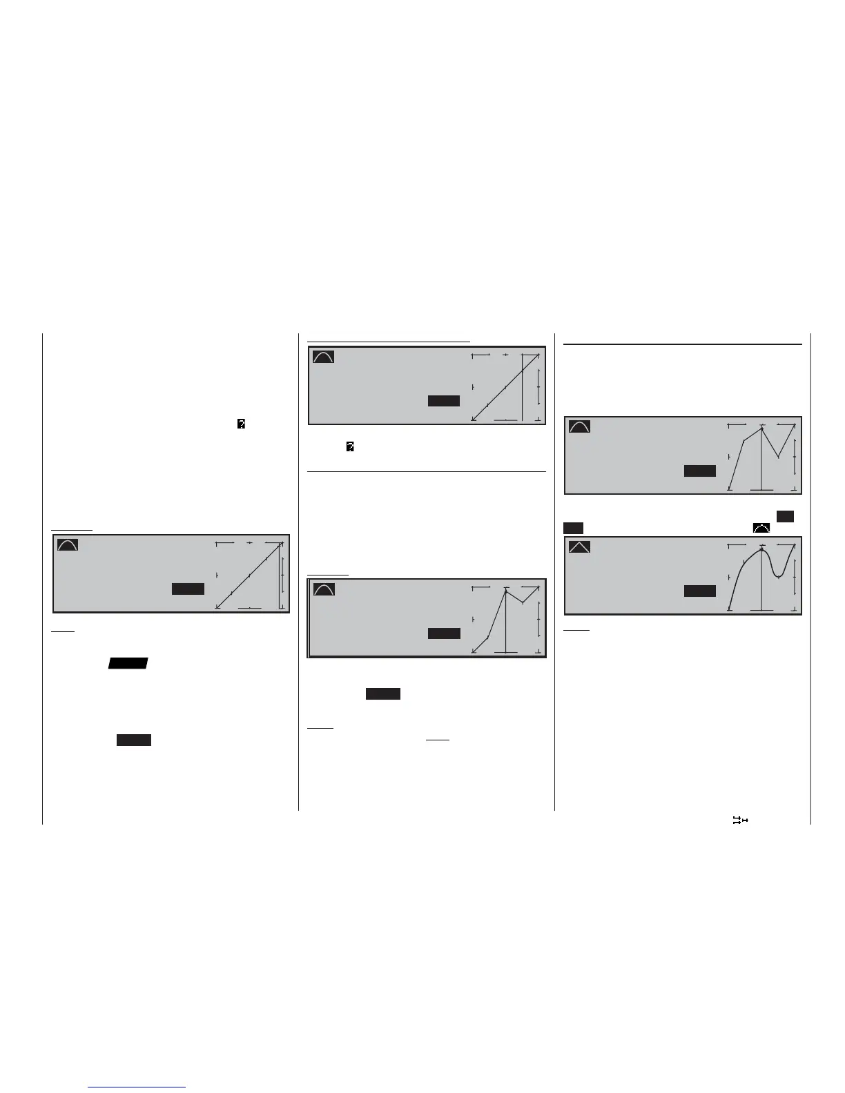
Rounding off the collective pitch curve
In the following example the reference points have
been set as follows, as described in the last section:
Reference point value 1 to +50% ,
Reference point value 2 to +90% and
Reference point value 3 to +0% .
P i t c h
I n p u t + 0 %
C u r v e O u t p u t + 9 0 %
o f f P o i n t 2
+ 9 0 %
®
O U T P U T
-
+
2
1 0 0
1
3
« N o r m a l »
This “jagged” curve profi le can be rounded off auto-
matically simply by pressing a button. Press the EN-
TER button adjacent to the “curve symbol” :
P i t c h
I n p u t + 0 %
C u r v e O u t p u t + 9 0 %
o f f P o i n t 2
+ 9 0 %
®
O U T P U T
-
+
2
1 0 0
1
3
« N o r m a l »
Note:
The curves shown here are only for demonstration
purposes, and by no means represent realistic thrott-
le / collective pitch curves.
Please refer to the programming examples on page
153 for a “real world” application.
The following three diagrams show typical three-point
collective pitch curves for different fl ight phases, such
as hover, aerobatics and 3-D fl ying.
The vertical bar refl ects the current stick position. Ple-
ase note that trim values greater than +100% and
less than -100% cannot be displayed on the screen.