99
Program description: Mixers
P i t c h = >
T h r s e t t i n g A R
- 9 0 %
T a i l r o t o r o f f s e t A R 0 %
G y r o s u p p r e s s i o n 0 %
S w a s h p l a t e r o t a t i o n 0
°
« A u t o r o t »
t
The adjustment facilities listed in this screen shot are
displayed in the Heli mixers menu when you switch
to the “Auto-rotation” phase or “Auto-rotation Ch1
Pos.”, i.e. auto-rotation must be active (see »Auxilia-
ry switch«, page 75).
Auto-rotation allows full-size and model helicopters
to land safely in a crisis, i.e. if the motor should fail. It
can also be used if the tail rotor should fail, in which
case cutting the motor and carrying out an auto-ro-
tation landing is the only possible way of avoiding an
uncontrollable high-speed rotation around the vertical
axis, invariably terminating in a catastrophic crash.
During an auto-rotation descent the main rotor is not
driven by the motor; it is kept spinning only by the air-
fl ow through the rotor plane caused by the fast des-
cent.
The rotational energy stored in the still spinning rotor
can be exploited to allow the machine to fl are out, but
this can only be done once. For this reason “autos”
are only likely to be successful if the pilot has plenty
of experience in handling model helicopters, and has
also carefully set up the functions listed above.
Once you have suffi cient experience, you should
practise auto-rotation landings at regular intervals, not
only so that you can demonstrate your all-round fl ying
skill by fl ying the manoeuvre in competitions, but also
so that you are in a position to land the helicopter un-
damaged from a great height if the motor should fail.
For this purpose the program provides a range of ad-
justment facilities which are designed to help you fl y
your helicopter in its unpowered state.
Helicopter mixer
Auto-rotation settings
Please note that the auto-rotation setting takes the
form of a complete fourth flight phase, for which all
the adjustment facilities are available which can be
varied separately for all flight phases, i.e. transmitter
control settings, trims, collective pitch curve settings
etc.. Certain special features are also provided which
are not available in the powered flight phases. These
functions are:
• AR throttle position:
Disconnection of the throttle servo from the coll-
ective pitch control system. In this case the thrott-
le servo takes up the “-90%” position shown in the
illustration. For further notes see the “Throttle set-
ting” section.
• Tail rotor offset:
Sets the tail rotor blade pitch to a value within the
range -125% to +125%.
(CLEAR = 0%.)
The Channel 1 tail rotor mixer is switched off for
auto-rotation. For notes on defi ning this value see
the “Tail rotor setting” section.
Collective pitch setting: “Pitch”
In powered fl ight the maximum blade pitch angle is li-
mited by the motor power which is available; however,
in auto-rotation the angle is only limited by the point
at which the airfl ow over the main rotor blades breaks
away. Nevertheless, to provide suffi cient upthrust
even when rotational speed is falling off, it is neces-
sary to set a greater maximum collective pitch value.
Start by setting a value which is about 10 to 20% hig-
her than the normal collective pitch maximum, to pre-
vent the helicopter ballooning up again during the fl a-
re following the auto-rotation descent. If this happens,
the rotational speed of the main rotor will quickly de-
cline to the point where it collapses, and the helicop-
ter ends up crashing to the ground from a considerab-
le height.
Under certain circumstances the collective pitch mi-
nimum setting may also differ from the normal fl ight
setting; this depends on your piloting style for nor-
mal fl ying. In any case you must set a suffi ciently ge-
nerous collective pitch minimum value for auto-rota-
tion to ensure that your model can be brought from
forward fl ight at moderate speed into a descent of
around 60° ... 70° when collective pitch is reduced to
minimum.
Most helicopter pilots already use such a setting for
normal fl ying, and if this applies to you, you can simp-
ly adopt the same value.
If the angle is too shallow, increase the value, and
vice versa.
For auto-rotation the collective pitch stick itself may
not be positioned right at the bottom of its travel; in-
stead it is typically between the hover position and
the bottom end-point, giving the pilot scope for cor-
rection if necessary, i.e. the chance to adjust the
model’s pitch inclination using the pitch-axis control.
You can shorten the approach by pulling back on the
pitch-axis stick and gently reducing collective pitch, or
alternatively extend the approach by pushing forward
on the pitch-axis stick and gently increasing collecti-
ve pitch.
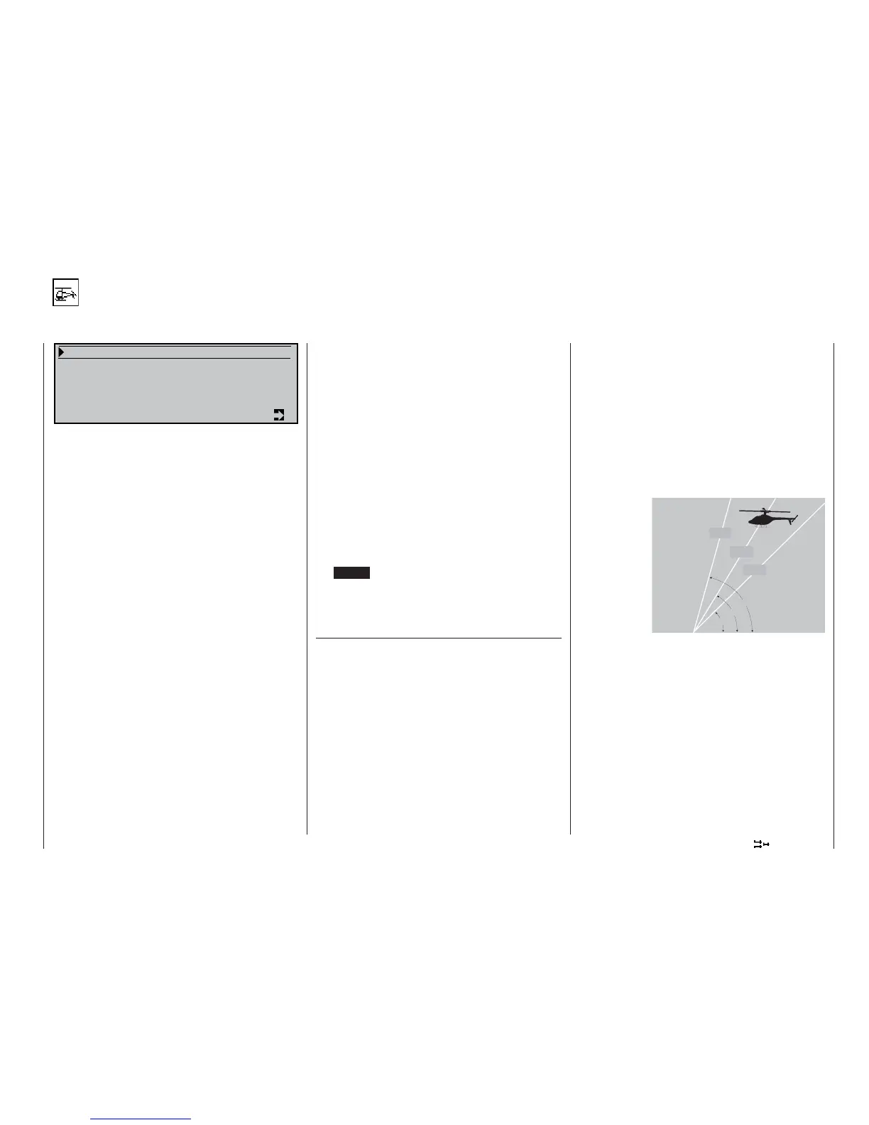
Approach angle under
varying wind conditions.
45°
60°
75°
Approach angle:
strong
wind
medium
wind
without
wind