Programming examples
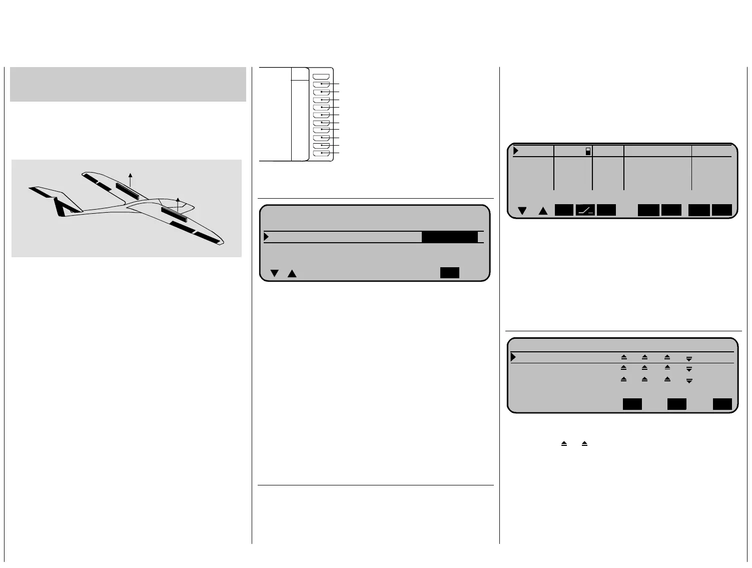
Application of flight phases
Example 2
Glider with 4-Wing-Servos, 2 Air-brake-servos
and Tow Release
We show you in the second example how you can
extend the basic set up to a specific application –
here thermal flight – with the aid of the flight phase
programming in very simple steps.
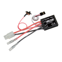
Bremsklappe links
Wölbklappe rechts
Wölbklappe links
Seitenruder
Querruder links
Höhenruder
Querruder rechts
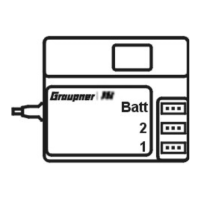
Batt
Bremsklappe rechts
Schleppkupplung
9
8
7
6
5
4
3
2
1
10
frei
PPM- oder PCM-Empfänger
elect in ...
QR
WK
HR
SR
WK
QR
ttings« You enter the model
assumes that you have done the
mechanical adjustments a
correct servo direction. Ch ain
and if found incorrect you
by swopping servo output
or just do it in Code 23 »
S
As the fine tuning of a mod
recommend to use the in
switch
« available trim- an
This programming example is relevant to the
Start with the programming of a new model memory.
In Code 21 »
Basic se
name, the control mode and the receiver type. The
following example
s well as selecting the
eck those settings ag
can change the direction
connection to the receiver
ervo adjust«.
el is done in flight , we
Code 49 »
Auxiliary
d INC / DEC-Switch
instead of the rotary selector , see page 20.
receiver connections as shown in the following
sketch:
S
Code 22 »Model type«, page 13
M O D E L L T Y P
Leitwerk normal
Querruder/Wölbklappen
2 QR
2 WK
Bremse Offset +90% Eingang 1
SEL
first the tail type “normal“. In the line Aileron/flap you
select “2 Al 2 Fl“. In the line “Brake“ you select
“input 1“. Later on we want to use the CH 1 stick as
r the two air-brake servos connected to
output 1+8. With the offset adjustment you enter the
he air-brakes to
be fully retracted at that setting of the control stick.
The remaining travel from 90% to the full foreward
position of the stick has no further response. With
that you ensure that the air-brakes are not popping
out with a minor position error if the control stick is
not fully foreward. At the same time the active travel
of the control stick is expanded to 100%.
controller fo
neutral point to + 90% if you want t
In Menu ...
Code 32 »Control adjust«, page 18
You adjust all inputs to “free“ except input 9 which
we will use for the tow release. All others are n
longer of use here. Select for input 9 an auxiliary
switch for the activation of the tow release.
With “- travel +“ you ca
o
n adjust the control throw for
the two end positions of the switch. Check it out with
a short push on the rotary knob in »
Servo display«
Eing. 9 2
0% +100%+100% 0.0 0.0
-Zeit+
Eing.10 frei
0% +100%+100% 0.0 0.0
Eing.11 frei
0% +100%+100% 0.0 0.0
Eing.12 frei
0% +100%+100% 0.0 0.0
Offset - Weg +
ASY
SYM
SEL ASY
SYM
SEL
As the CH 1 control stick must (besides servo1) also
move servo 8, you couple that function with a dual
mixer.
Change to ...
Code 75 »Dual mixer«, handbook mc-24/1 page
97
K R E U Z M I S C H E R
Mischer 1 K1
8
0 %
Mischer 2 ?? ?? 0%
Mischer 2 ?? ?? 0%
Diff.
SE
LSELSEL
The symbol
K1
means that by movement of th
CH 1 stick, servos 1+8 (the
e
e in
two air-brakes) mov
the same direction.
Programming examples 38
 Loading...