In the Multi-Flap-Menu of ...
Code 71 “Wing mixer“, page 28
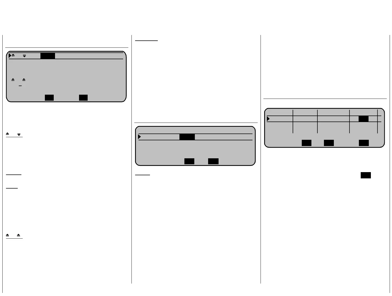
SEL
SEL SEL
QR ++80% +60%
QR-Tr. +100% +50%
Diff. +50% +30%
WK-Pos 0% 0%
WK 0% 0% 0% 0%
HR >WK +10% +10% +15% +15%
«normal »
QR WK
adjust the mixing values for the 4 wing servos. The
here displayed parameters depend on the model
and have to be evaluated during test flights.
Change now to line:
QR
: Here we adjust the amount of aileron
coupling for the two “Ail“ and “Fl“ by
movement of the aileron stick in%.
Before you set these values make sure
to check on the correct direction of
control throw.
Ail-tr.: Select the desired trim value from
aileron trim lever to “Al“ and “Fl“.
the
Diff.: Adjust the d
“Al“ and “Fl“.
esired differential value for
Page 75 in the mc-24/1
tion of the
“Differential“.
The adjustment range of -100% and
+100% allows for the selection of the
correct differential direction independant
of control direction on ailerons and flaps.
handbook explains the func
WK
: The ailerons and flaps can not be
controlled as camber flaps as we had
ve).
is
selected “free“ for input 6 (further abo
The standard values can remain in th
line, but we have set the values for the
camber flaps to “0% / 0%“ to make it
easier to view the functions.
HR->WK:
This mixer moves the ailerons and/or
camber flaps with movement of the
elevator control stick. Select the mixing
direction so that by pulling (back) on the
elevator stick the ailerons and camber
flaps move “down“ and if desired “up“
with the elevator stick pushed down
ents by pushing briefly on the
(foreward).
Check these adjustm
rotary select knob in »
Servo display«.
Now change within the wing mixer menu to the ..
Brake adjustments, page 30
QR WK WK2
B R E M S E I N S T E L L U N G E N
Butterfly
+40%
+30%
Diff.-Redukt.
+8
0% 0%
HR-Kurve =>
Crow: Further above we selected the CH 1 stick
w
ent
nt
so that both ailerons move upwards and
both flaps move downward. A short push
lector lets you check in
e end of the
stick travel (full foreward position).
If required, check again all control movements and
adjust if neccessary in Code 23 »
Servo adjust« the
sevo centre, servo travel and servo travel limit.
d.
n the following procedure we are programming a
econd flight phase for the “Thermal“ flight which
for the control of the brake flaps. No
you select here by which amount the
ailerons and faps will travel by movem
of the brake stick. Make your adjustme
on the rotary se
the “Sevo display“ the selected values
but also importantly that the brake control
stick has no influence on the “Crow“ from
the brake offset (90%) to th
Perhaps now the time has come for the first test
flying providing all global functions - (flight phase
dependant adjustments) - have been complete
I
s
requires some different control adjustments.
Change to ...
Code 51 »Phase settings«, page 22
Phase 1 normal 2.0s
Phase 2 Thermik
2.0s
-
Phase 3 0
.0s
-
Phase 4 0.0s -
Name Flugph. Uhr Umsch. Zeit
SELSEL SEL
or the just completed programming of phase 1 –
al“ with
F
the normal phase –we select the name “norm
the rotary controller after first pushing the S
(You can create your own phase name in Code 91
We select the name “Thermal“ for phase 2. In th
right column you enter a delay time to switch from
any other phase into the thermal phase in order to
avoid abrupt changes. You have to experiment a
EL –key.
).
e
set little to get the time delay to your liking. We have
the delay to 2sec. in our example.
Programming examples 39
 Loading...