EasyManuals Logo

Gree FLEXX Series Service Manual

Gree FLEXX Series
121 pages
To Next Page IconTo Next Page
To Previous Page IconTo Previous Page
Page #78 background imageLoading...
Page #78 background image
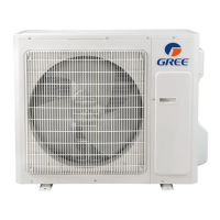
GREE DC INVERTER HEAT PUMP CONDENSING UNIT
75
Removal of compressor/gas liquid separator
NOTE: Before removing the compressor/gas liquid separator, make sure there is no refrigerant in the pipeline and power is cut off.
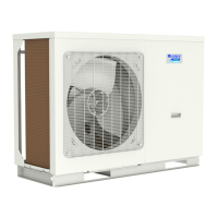
Step
Picture
Work instruction
5. Install the new
compressor/gas liquid
separator onto the chassis.
Screws
After replacing the
compressor/gas liquid
separator, tighten up the
base screw nuts.
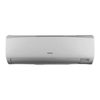
6. Connect the welding
interfaces of
compressor/gas liquid
separator to the pipeline.
Weld the connection pipes
of compressor so as to
connect them to the
compressor.
NOTE: When replacing
the compressor, avoid
touching the nearby
pipeline and components.
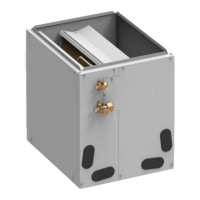
7. Connect the compressor
wires.
Connect the compressor
wires to the wire terminals
on the top of compressor.
NOTE: When connecting
the wires, be sure to
match the colors with the
corresponding wire
terminals.

Other manuals for Gree FLEXX Series

Questions and Answers:

Question and Answer IconNeed help?

Do you have a question about the Gree FLEXX Series and is the answer not in the manual?

Gree FLEXX Series Specifications

General IconGeneral
TypeHeat Pump
SeriesFLEXX
SEERUp to 20
HSPFUp to 10
RefrigerantR410A
Heating Operation Range-22°F to 75°F
Cooling Operation Range5°F to 122°F
Operating Temperature Range (Heating)-22°F to 75°F
Operating Temperature Range (Cooling)5°F to 122°F
Energy Efficiency Ratio (EER)Up to 12.5
Dimensions (Outdoor Unit)Varies by model
Weight (Outdoor Unit)Varies by model
Compressor TypeInverter
Power Supply208/230V, 1Ph, 60Hz
Noise LevelAs low as 55 dB(A)

Related product manuals