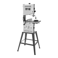
Model G0771Z (Mfd. Since 01/21)
-71-
Miter Gauge
Adjustments
The miter gauge is equipped with stop screws that
allow you to easily adjust the miter gauge 0°– 30°
left, 90°, and 0°–45° right. The stop screws con-
tact the shaft, which moves in or out of the way
for adjustments.
Tools Needed Qty
Phillips Head Screwdriver .................................. 1
90° Square ........................................................ 1
45° Square ........................................................ 1
30° Square ........................................................ 1
Wrench 8mm ..................................................... 1
Checking/Setting 90° Stops
1. DISCONNECT SAW FROM POWER!
2. Slide miter gauge into T-slot on table.
3. Place square evenly against face of miter
gauge and blade, as shown in Figure 128.
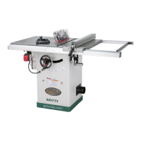
Figure 128. Checking 90° stop on miter gauge.
Square
Miter Gauge
Blade
— If square touches miter body and body
of blade evenly at same time, then it is
square to blade. No adjustments are nec-
essary.
— If square does not touch miter body and
blade evenly, then proceed to Step 5.
4. Remove miter gauge from miter slot.
Checking/Setting 45° Stops
Follow the same process with the 45° and 30°
stops that you followed with the 90°, except using
a 45° square or adjustable square to verify that
the miter body is 45° to the blade.
6. Using a square, position miter shaft at 90° to
miter gauge body.
7. Tighten stop plate screws.
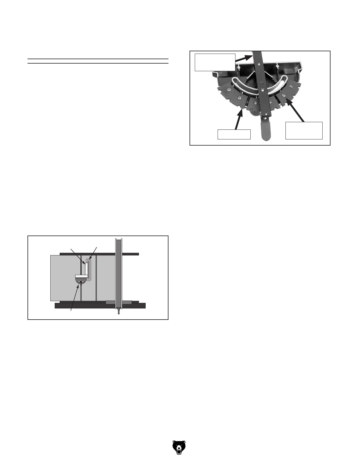
Figure 129. Checking 45° stop on miter gauge.
Miter Gauge
Shaft
Stop Plate
Adjustment
Screws
5. Loosen two Phillips head screws that secure
90° stop plate (see Figure 129).