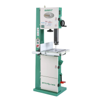
Model G0803Z (Mfd. Since 12/18)
-15-
Assembly
LACERATION HAZARD!
Bandsaw blades and some
sheet metal parts are
sharp. Wear heavy leather
gloves while handling to
reduce risk of being cut.
To assemble bandsaw:
1.
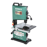
Attach (4) rubber feet to bandsaw base (see
Figure 11). Rubber feet simply press onto
corners of base.
6.
Re-install components removed in Step 2.
DO NOT fully tighten yet.
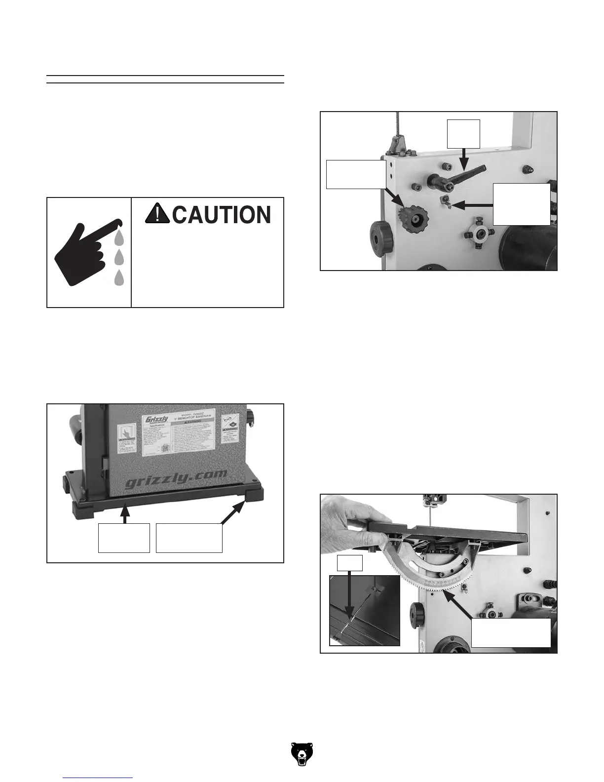
Figure 12. Location of table controls that must
be removed or adjusted.
Adjustment
Knob
Lock
Lever
Indicator
Positioned
Down
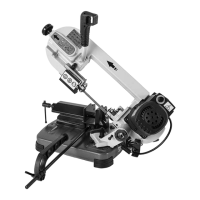
Figure 13. Table assembly positioned on saw.
Gap
Table/Trunnion
Assembly
3. Turn guide post adjustment knob (see
Figure 3 on Page 4 for location) counter-
clockwise to raise guide post all the way up.
4.
Remove wing bolt, lock washer, flat washer,
and D-nut from table assembly. Make note of
how fasteners secure to fence assembly for
re-installation later.
5.
Using gap in table (see Figure 13), slide
table assembly through blade and rotate
assembly 90°. Position assembly as shown
in
Figure 13.
The machine must be fully assembled before it
can be operated. Before beginning the assembly
process, refer to
Needed for Setup
listed items.
To ensure the assembly process
goes smoothly, first clean any
parts that are
cov-
ered or coated in heavy-duty rust preventative (if
applicable).
2. Loosen scale indicator and position it down
(see
Figure 12), then remove table tilt lock
lever, flat washer, table tilt adjustment knob,
and shoulder bolt with spring (see
Figure 12).
Figure 11. Rubber feet attached to base.
Rubber Foot
(1 of 4)
Bandsaw
Base