Model G1033/X/Z (Mfd. Since 02/19)
-39-
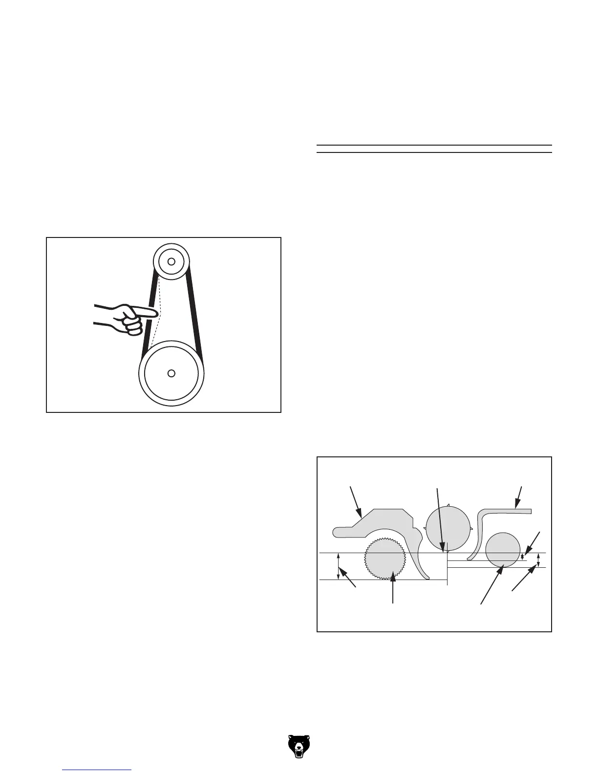
Setting Feed Roller,
Chip Breaker &
Pressure Bar
Heights
A & B
Infeed
Roller
Outfeed
Roller
Pressure
Bar
Chip
Breaker
C
D
BDC
(Bottom Dead Center)
Figure 50. Planer component recommended
clearances (illustration is not to scale).
Dist. Below Knife/Insert at BDC (Figure 50)
A. Infeed Roller ....................................... 0.040"
B. Chip Breaker.......................................0.040"
C. Pressure Bar.......................................0.008"
D. Outfeed Roller .................................... 0.020"
It is essential that the feed rollers, chip breaker,
and pressure bar are set at the correct distance
below the cutterhead knives/inserts at BDC (bot-
tom dead center) to ensure that the workpiece
moves through the planer evenly and the correct
distance from the cutterhead knives/inserts.
To ensure accurate results and make the adjust-
ment process quicker and easier, we recommend
using a Rotacator for these adjustments (refer to
Page 30).
If a Rotacator is not available, a 6' 2x4 cut into two
even-sized pieces and a feeler gauge set can be
used, but care must be taken when jointing the
wood to achieve accurate results.
4. If V-belts need to be replaced, raise motor to
release belt tension (see next step for instruc-
tions), roll them off pulleys, then replace with
a matched set of three.
5. To adjust V-belt tension, loosen both top
motor mount hex nuts (see Figure 48 on
Page 38), then adjust bottom hex nuts to
raise or lower motor.
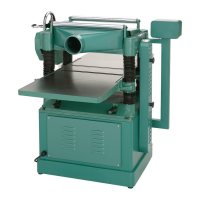
Note: V-belts are correctly tensioned when
there is approximately
3
⁄4" deflection when
moderate pressure is applied to them midway
between pulleys, as illustrated in Figure 49.
Cutterhead
Pulley
Approximately
3
⁄
4
" Deflection
Motor
Pulley
Figure 49. Belt deflection when V-belts are
correctly tensioned.
6. After V-belts are correctly tensioned, tighten
top motor mount hex nuts, then re-install
cabinet cover and belt cover.
 Loading...