SPHInverter
ACGRID
L L
EPS OUTPUT
N N
E E
Sensor
L LN NE E
Battery
L
N
PE
PV
EPS
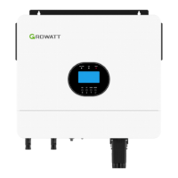
Step5: To remove the AC connector, press the bayonet out of the slot with a small
screwdriver and pull it out, or unscrew the threaded sleeve, then pull it out.
Chart 5.15
The recommended wiring diagram is as follows:
Chart 5.16
23
24
The Inverter Side
Unlock the
housing
The Inverter Side
Unlock the housing
Chart 5.17
Note: This diagram A is an example for grid system without special requirement on
electrical wiring connection.
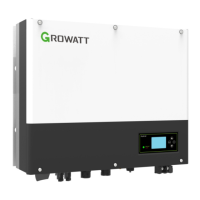
Note: This diagram B is an example for Australian and New Zealand grid system
where neutral line can't be switched.
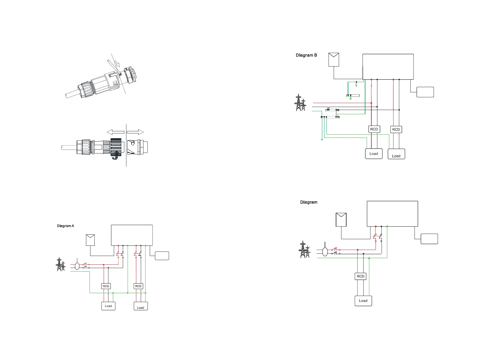
Note: This diagram C is an example for customer who only wants to use the on grid
storage system.
Chart 5.18
S
PHI nv
e
r
t
e
r
A
CG
RID
L N E
Se
n
so
r
L N E
B
a
tt
e
r
y
L
N
PE
PV
C
L L
SPHInverter
ON GRID EPS
N N
L
L
N
N
P
E
Battery
L
N
PE
PV
E
P
S
PE
E-BAR
E-BAR
E-N LINK
PE
 Loading...