× If you want to use on grid only, please refer to chart 5.17 connect
with AC grid and float EPS OUTPUT.
× If you have no battery now, you can also float BAT terminal, and this
hybrid inverter will only work like a PV inverter.
× If you want to use both on grid power and backup power, please
refer to chart 5.15 and 5.16 connect with AC grid and EPS OUTPUT like
the chart show.
× On grid terminal and off grid terminal can't directly connect
together.
× Off Grid terminal can't connect to grid.
× If you want to use on grid and off grid, you can use ATS (automatic
transfer switch) like chart 5.15 and 5.16 before or ask Growatt for help
to connect them.
× The first start of system needs Grid power.
NOTE: The inverter has the function of detecting residual current and
protecting the inverter against residual current. If your inverter must
equip a AC breaker which has the function of detecting residual current,
you must choose a Type A RCD breaker with the rating residual current
more than 300mA.
Warning
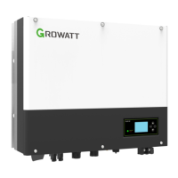
5.4.4 Connection of battery terminal
Install battery cable steps are as follows:
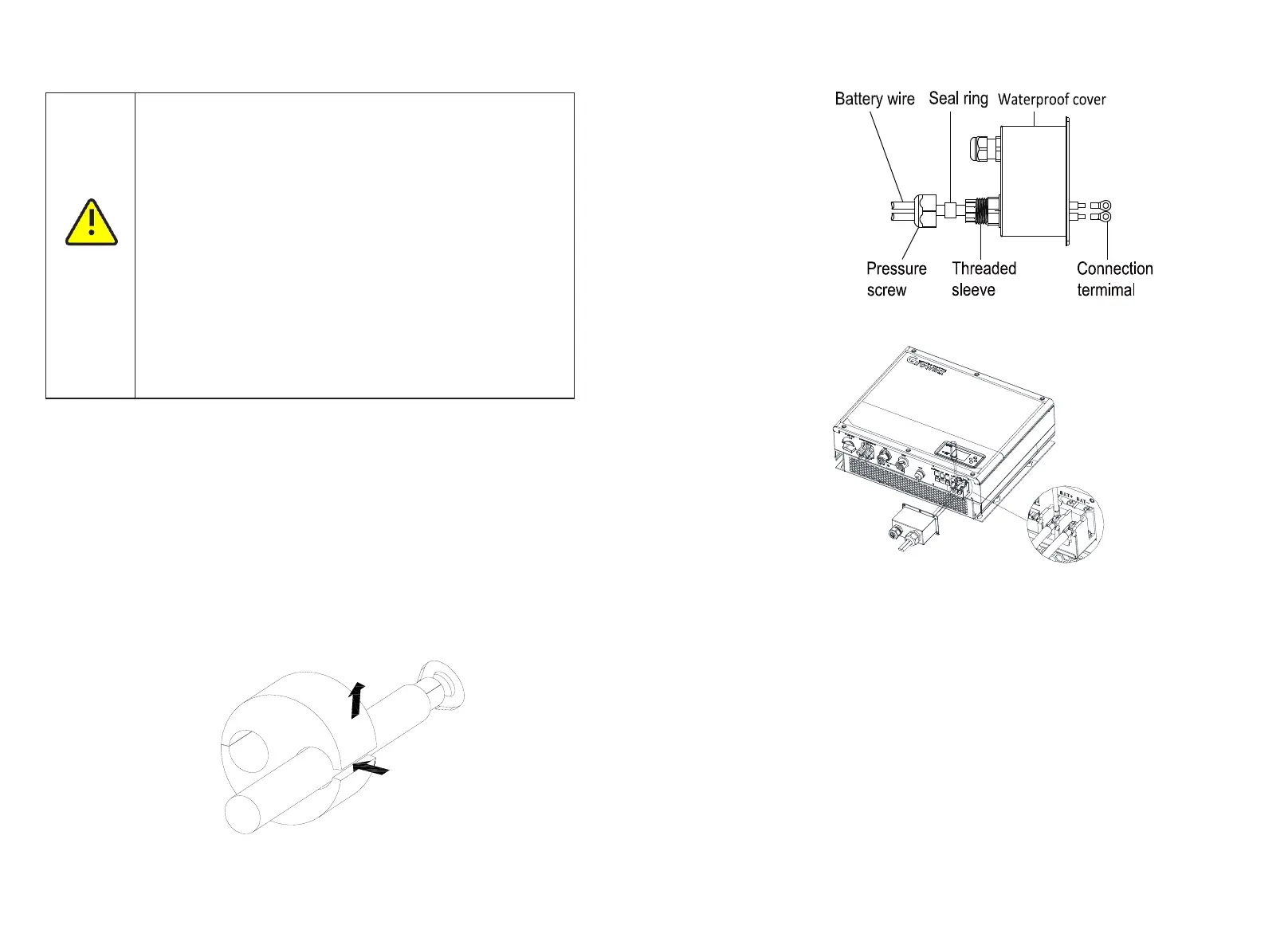
1.Unscrew the swivel nut from the cable gland.
2.Thread the swivel nut over the battery cable.
3.Press the cable support sleeve out of the cable gland.
4.Remove the filler plug from the cable support sleeve.
5.Route the network cable through an opening in the cable support sleeve.
6.Thread the network cable through the cable gland.
7.Thread cables into connection terminal, then press the terminal by relevant tools and
make sure battery cables are firmly (Growatt lithium battery contains a battery cable in
the original packing).
8.Connect positive pole (+) of battery cable to battery positive terminal (+) of the
inverter, connect negative pole (-) of battery cable to battery negative terminal (-).
9.Continue to install other cables.
Chart 5.19
25
26
Chart 5.20
Note:We suggest the distance between battery and SPH no longer than 1.5m, and the
power line area must be larger than 5 AWG.
5.4.5 Connection of CT terminal
There is a CT in SPH inverter monitoring the power consumption situation of residential
users, the CT terminal connection steps are as follows:
1.Unscrew the swivel nut from the cable gland.
2.Thread the swivel nut over the “CT” cable.
3.Press the cable support sleeve out of the cable gland.
4.Remove the filler plug from the cable support sleeve.
5.Route the “CT” cable through an opening in the cable support sleeve.
6.Thread the “CT” cable through the cable gland.
7.Insert the RJ45 plug of the network cable into the “CT1/METER1” pin connector on the
inverter until it snaps into place.
8.If no other cables need to be installed, lock the waterproof cover to the inverter with
screws.
9.Screw the swivel nut onto the waterproof cover.
Chart 5.21
 Loading...