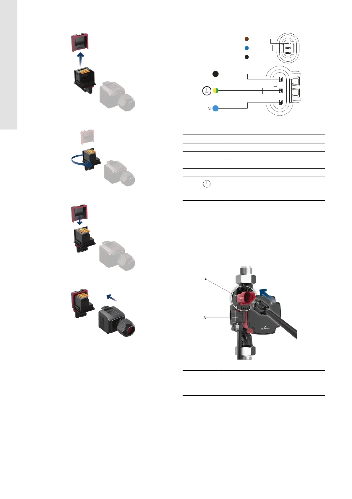
2. Lift the back plate of the plug.
TM089767
3. Turn the plug 90° left.
TM089768
4. Place the back plate in the 90° position.
TM089769
5. Slide the cover back on.
TM089770
Related information
5.1 Assembling the power plug
5.2
Wiring diagram
TM089307
Power and signal plug
Pos. Description Wire colour
IN PWM input Brown
REF Signal reference Blue
OUT PWM output Black
L Phase Black or brown
Earth Yellow/green
N Neutral Blue
5.3 Control box connections
All control boxes have two electrical inlets placed on one side:
• power inlet
• signal inlet.
The signal inlet is galvanically isolated from the power supply of
the circulator pump. There is therefore no risk of electrical shock if
touching the signal inlet. Furthermore, the signal plug is "water tight"
protecting against ingress of liquids into the control box.
TM089771
Pos.
Description
A Power inlet (superseal)
B Signal inlet (mini superseal)
10
English (GB)