8.6.5 PWM feedback signal
The PWM feedback signal offers the same pump information as in
bus systems:
• current power consumption or flow estimation
• warning
• alarm
• operating status.
Alarms on power consumption
Alarm output signals are available because some PWM output duty
cycles are dedicated to alarm information. If a supply voltage is
measured below the specified supply voltage range, the output duty
cycle is set to 75 %. If the rotor is locked due to deposits in the
hydraulics, the output duty cycle is set to 90 % as this alarm has a
higher priority.
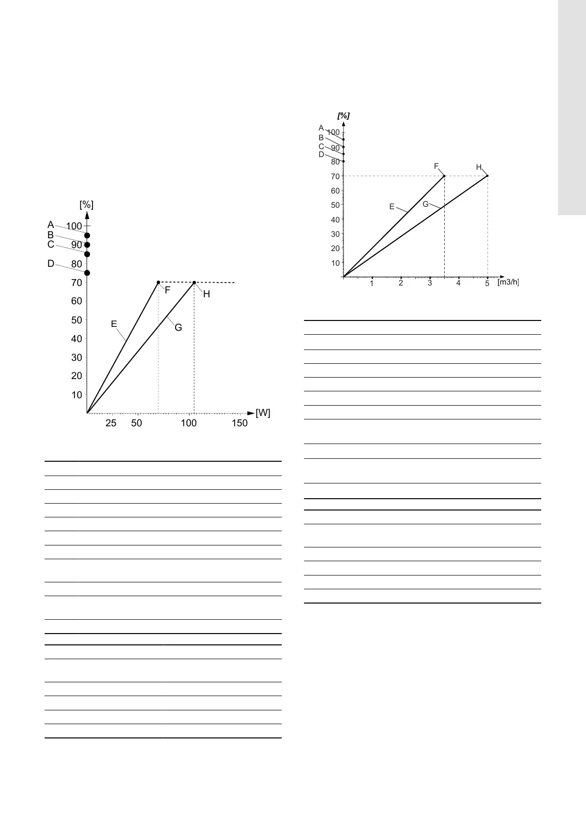
TM088572
PWM feedback signal, power consumption
Pos. Description
X-axis Output power consumption [W]
Y-axis Output duty cycle in percentage [%]
A Standby (stop)
B Alarm stop: fault, blocked pump
C Alarm stop: electrical fault
D Warning
E
Slope: 1 W / % PWM signal
Valid for ALPHA2 GO XX-40 and XX-60
F Saturation at 70 W
G
Slope: 1.5 W / % PWM signal
Valid for ALPHA2 GO XX-75 and XX-90
H Saturation at 105 W
PWM output duty cycle Pump information
95 %
Standby (stop) by PWM duty
cycle
90 % Alarm, stop, blocked error
85 % Alarm, stop, electrical error
75 % Warning
0-70 % Operating range
Output frequency: 75 Hz ± 5 %.
Alarms on flow estimation
Alarm output signals are available because some PWM output duty
cycles are dedicated to alarm information. If a supply voltage is
measured below the specified supply voltage range, the output duty
cycle is set to 75 %. If the rotor is locked due to deposits in the
hydraulics, the output duty cycle is set to 90 % as this alarm has a
higher priority.
TM090127
PWM feedback signal, flow estimation
Pos. Description
X-axis
Output power consumption [m
3
/h]
Y-axis Output duty cycle in percentage [%]
A Standby (stop)
B Alarm stop: fault, blocked pump
C Alarm stop: electrical fault
D Dry running
E
Slope: 0.05 m
3
/h / % PWM signal
Valid for ALPHA2 GO XX-40 and XX-60
F
Saturation at 3.5 m
3
/h
G
Slope: 0.07 m
3
/h / % PWM signal
Valid for ALPHA2 GO XX-75 and XX-90
H
Saturation at 5.0 m
3
/h
PWM output duty cycle Pump information
95 %
Standby (stop) by PWM duty
cycle
90 % Alarm, stop, blocked error
85 % Alarm, stop, electrical error
80 % Dry running
0-70 % Operating range
Output frequency: 75 Hz ± 5 %.
17
English (GB)