8.6 PWM signal
A PWM (Pulse Width Modulation) signal is used in pumps to control
their speed and flow rate efficiently. External PWM control mode
can only be selected via Grundfos GO.
8.6.1 Installation with PWM signal
In a replacement situation where the old pump was controlled with a
PWM signal, the ALPHA2 GO pump only needs to be connected to
power and an external signal and configurated with Grundfos GO to
be ready to operate.
In a new pump setup where the external PWM signal is to be
configured, you need the following information:
1. PWM signal specifications:
• Frequency: The PWM signal frequency must match the
requirements of the pump.
• Duty cycle: This determines the speed of the pump.
• Voltage levels: Ensure that the PWM signal voltage levels
are matching the requirements of the pump.
2. Feedback mechanism:
• PWM feedback signal: This signal can provide information
about the pump's operating status, such as power
consumption and speed.
• Feedback mechanisms in circulator pumps with PWM control
are essential for monitoring and adjusting the pump's
performance.
a. Operating status:
- The feedback signal provides real-time information
about the pump's operating status. For example, it can
indicate whether the pump is running, its speed and any
potential issues.
b. Flow or power consumption:
- The feedback signal can reflect the flow or power
consumption of the pump. This helps in monitoring
energy usage and ensuring the pump operates
efficiently.
c. Error detection:
- If the pump encounters an issue, such as a blocked
rotor or low power voltage, the feedback signal can
indicate this by changing its duty cycle. For instance,
a blocked rotor will set the feedback signal to 90 %,
triggering a warning.
d. System integration:
- The feedback signal can be used to compare the
actual operating status of the pump with the desired
settings. This allows for precise control and adjustments
to maintain optimal performance.
e. Protection features:
- In the event of signal loss or cable breakage, the
feedback mechanism ensures that the pump operates
in the safest possible way, depending on the system in
which the pump is mounted.
These feedback mechanisms are crucial for maintaining
the reliability and efficiency of circulator pumps in various
applications, such as heating systems, heat pumps and solar
systems.
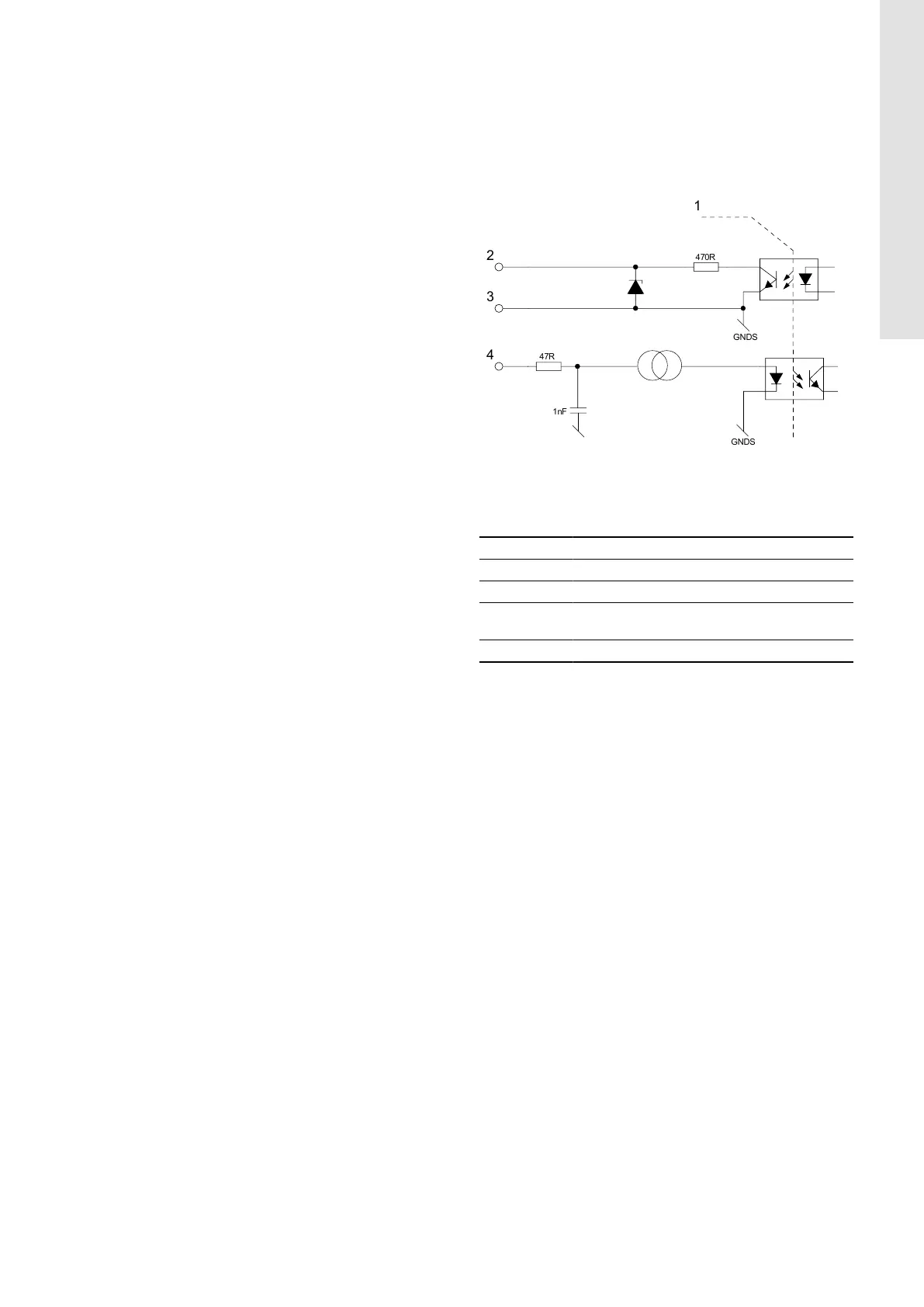
8.6.2
PWM interface
The PWM interface consists of an galvanically isolated circuit
connecting the external control signal to the pump. The interface
translates the external signal into a signal type that the
microprocessor can understand.
The galvanically isolated interface ensures that the user cannot
get into contact with dangerous voltage if the signal wires are
touched when the pump is connected to power.
TM085420
Schematic drawing, equivalent interface
Pos. Description
1 Galvanic isolation
2 PWM output
3
Signal reference (without connection to protective
earth)
4 PWM input
15
English (GB)