7.1.1 Overview of LEDs
The LEDs indicate the control mode, setting and operating status.
Factory setting
The pump is factory set to proportional pressure, AUTOADAPT.
Active light fields Description
Advanced mode
The control mode is set via Grundfos GO.
When the pump is set via Grundfos GO, the
icon is lit and the control modes and
settings on the operating panel are
switched off.
Proportional-pressure mode
Constant-pressure mode
Setting I
Setting II
Setting III
AUTOADAPT mode
The pump is set to STOP in Grundfos GO
or by an active PWM stop signal.
When the symbols for the constant-pressure and proportional-
pressure modes are off, the pump is running in constant-curve
mode.
Related information
7.1 Operating panel
7.1.2
Power saving
In order to lower the energy consumption and heat generation, the
operating panel goes into power saving mode after 15 minutes of
inactivity. The power saving mode switches off the LEDs in the
middle including the dot and the units.
• To reactivate the pump from the power saving mode, press the
Selection button.
• If a warning or an alarm is present during power saving mode,
only the yellow or red LED will be lit. Press the Selection button
to see the error code.
• If the operating panel is locked via Grundfos GO, the lock icon
on the operating panel will be lit in power saving mode.
• The power saving function can be disabled via Grundfos GO.
8. Control modes
ALPHA2 GO can be set to the following control modes:
• constant curve
• proportional pressure
• constant pressure
• constant flow
• external control (PWM)
• replacement mode.
All control modes can be set in Grundfos GO. However, only
constant curve, constant pressure and proportional pressure can
be set on the operating panel.
Related information
7.1 Operating panel
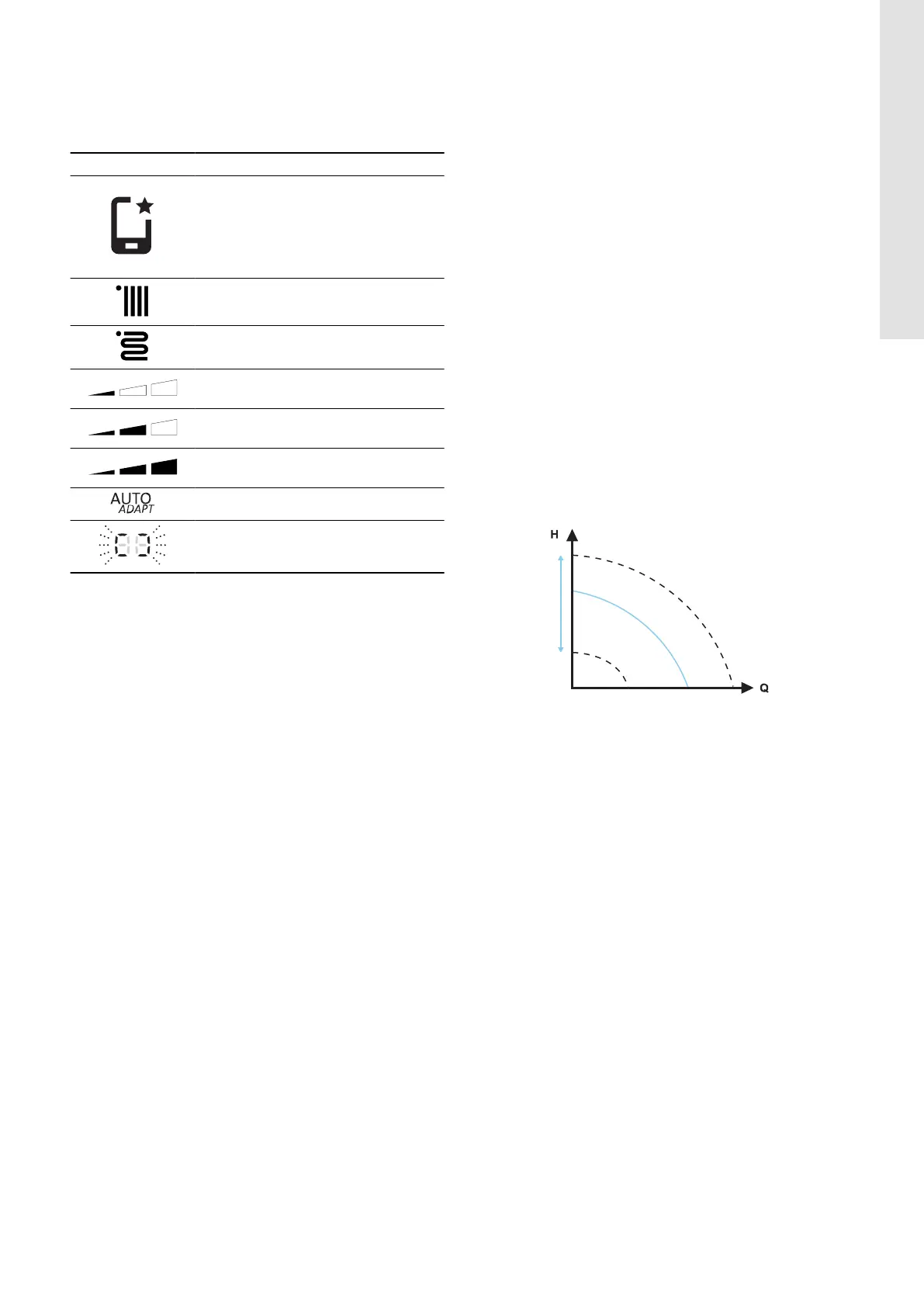
8.1 Constant curve
In the constant-curve mode, the pump runs at a constant curve,
which means that it runs at constant speed or power. The pump
performance follows the selected constant curve. This control mode
is especially suitable in applications where the characteristics of
the heating system are steady, and the emitters require a constant
flow. The selection of the constant-curve setting depends on the
characteristics of the heating system and the actual required flow
and heat demand.
The curve's setpoint is user defined in Grundfos GO. The speed in
percentage of maximum speed can be chosen anywhere between
the minimum and maximum constant curve in intervals of 1 %.
TM071005
Constant curve
13
English (GB)