English (US)
8
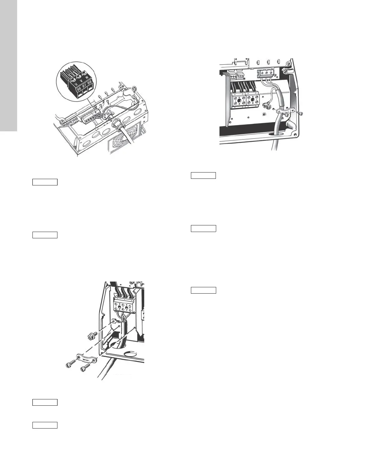
1. Connect the ground conductor to terminal 99 (PE), see fig. 13.
2. Connect the motor conductors to terminals 96 (U), 97 (V),
98 (W) of the motor plug.
3. Put the motor plug into the socket marked MOTOR.
4. Fix the screened cable with a cable clamp.
Fig. 13 Motor connection, A5
7.2.6 Enclosures B1 and B2
For information about enclosure, see table in section
17.1 Enclosure.
Mains connection
1. Connect the ground conductor to terminal 95 (PE), see fig. 14.
2. Connect the mains conductors to terminals 91 (L1), 92 (L2),
93 (L3).
3. Fix the mains cable with a cable clamp.
Fig. 14 Mains connection, B1 and B2
Motor connection
1. Connect the ground conductor to terminal 99 (PE), see fig. 15.
2. Connect the motor conductors to terminals 96 (U), 97 (V),
98 (W).
3. Fix the screened cable with a cable clamp.
Fig. 15 Motor connection, B1 and B2
7.2.7 Enclosures B3 and B4
For information about enclosure, see table in section
17.1 Enclosure.
Mains connection
1. Connect the ground conductor to terminal 95 (PE).
See figs 16 and 17.
2. Connect the mains conductors to terminals 91 (L1), 92 (L2),
93 (L3).
3. Fix the mains cable with a cable clamp.
Motor connection
TM03 9018 2807
The cable screen must be exposed and in
physical contact with the mounting plate and
clamp.
Check that mains voltage and frequency
correspond to the values on the nameplate of the
CUE and the motor.
TM03 9019 2807
For single-phase connection, use L1 and L2.
The motor cable must be screened for the CUE to
meet EMC requirements.
TM03 9020 2807
The cable screen must be exposed and in
physical contact with the mounting plate and
clamp.
Check that mains voltage and frequency
correspond to the values on the nameplate of the
CUE and the motor.
The motor cable must be screened for the CUE to
meet EMC requirements.