English (GB)
12
5. Construction and functioning
This section includes detailed information on the production
process, as well as dosing control, measurement and flushing.
Several parameters and the settings at a mechanical ClO
2
pump
are explained.
Letter symbols used in this section
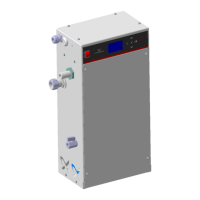
5.1 Installation schemes
5.1.1 System with measuring cell
Fig. 3 OCD-162 with measuring cell
A
ClO2
added quantity [mg/l]
Q
DPmax
max. dosing flow [l/h]
S
DP
stroke length [%]
C
ClO2
ClO
2
concentration in batch tank [g/l]
K
D
dosing coefficient [h/m
3
]
Q
WM
water meter flow [m
3
/h]
TM06 1096 1814
1 OCD-162
2 Main water line to be disinfected
3 Dilution water extraction device with isolating valve
4 Dilution water pipe
5 Dirt trap
6Water meter
7 Signal line of water meter
8 Injection unit
9 Dosing line
10 Measuring cell
11 Signal line of ClO
2
measurement
12 Measuring water extraction device
13 Measuring water pipe
18 Drain

 Loading...