English (GB)
30
6.6.2 External dosing pump
The external dosing pump is not a standard component.
1. Route the dosing line from the internal batch tank to the
external dosing pump, and connect it to the suction valve on
the external dosing pump.
2. Route the overflow line from the external dosing pump back to
the internal batch tank, and connect it.
3. Route the dosing line from the external dosing pump to the
injection unit, and connect it to the injection unit.
6.6.3 Measuring cell
1. Connect a hose to the extraction device in the main line, route
it to the measuring cell inlet, and connect it.
2. Connect another sample-water hose to the measuring cell
outlet, and route it into the drain.
For more detailed information, see the installation and operating
instructions for the measuring cell.
6.6.4 Measuring module
1. Connect a hose to the extraction device in the main line, route
it to the measuring module inlet, and connect it.
2. Connect another hose to the measuring module outlet, route it
to the injection unit in the main line, and connect it.
For more detailed information, see the installation and operating
instructions for the measuring module.
6.6.5 Bypass mixing module
1. Connect the dosing line from the dosing pump to the injection
unit in the bypass mixing module.
2. Connect a hose from the extraction device in the main line to
the bypass mixing module.
3. Connect another hose from the bypass mixing module to the
injection unit in the main line.
For more detailed information, see the installation and operating
instructions for the bypass mixing module.
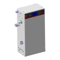
6.7 Electrical installation
Fig. 26 Control unit with cable glands
The following components can be connected at commissioning:
• Warning lamp or audible warning system
•Water meter
• Measuring cell
• Sample-water sensor from bypass measuring module
• Failure input, for example to a gas warning device
• Flow switch on bypass mixing module
• Dosing stop input, for example to a higher-level control system
• External batch tank
Passing a cable through a gland
1. Unfasten the two screws on the rectangular cover under the
control unit. Remove the cover.
2. Loosen the cable gland, and push the cable through.
3. Connect the cable as shown in the terminal connection plan,
see section 14. Terminal connections.
4. Tighten the cable gland by hand.
6.7.1 Water meter
The connections depend on the type of water meter (pulse signal
or current signal).
Connect the signal cable of the water meter to the control unit,
see section 14. Terminal connections.
Warning
Incorrect installation may result in personal injury
and damage to property.
Only authorised service staff may connect an
external dosing pump to the system.
Warning
Only authorised service staff may connect the
electronic components.
Warning
Risk of shock from damaged electronic components
(transport or installation damage).
Do not reach into the void behind the control unit. Do
not kink cables.
TM03 6926 4506

 Loading...