English (GB)
29
6.6 Hydraulic installation
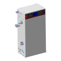
Fig. 23 OCD-162-05 (-10)
Fig. 24 OCD-162-30
Fig. 25 OCD-162-60
6.6.1 System frame
1. Close the dilution water extraction device.
2. Connect the dilution water hose to the extraction device, see
5.1 Installation schemes.
3. Route the dilution water hose to the system frame.
4. Connect the dilution water hose to the solenoid valve.
5. Route the ClO
2
hose from the multi-function valve on the
dosing pump to the injection unit (in the protective pipe
provided by the customer) and connect it.
6. Connect the hose from the internal batch tank to the drain
cock for flushing.
TM06 0638 0714
TM05 9974 0314
TM05 9975 0314
Pos. Description
1 Hose from the internal batch tank to the drain cock
2 Hose of suction lance
3 Dosing line from the dosing pump to the injection unit
4 Solenoid valve with connection for dilution water
Keep the hose as short as possible and avoid kinks!
Make sure that the pressure of the dilution water is >
3 bar when the solenoid valve is open.
Warning
If protective pipes for the dosing line are installed,
these may not be longer than 3 metres.
Risk of concentrated collection and dangerous
escape of ClO
2
gas.

 Loading...