English (GB)
60
11. Repair
This section includes the information of how to replace complete
components of the system. The order number of the spare parts
you find in section 15. Overview spare parts, maintenance kits
and accessories.
The following sections describe the complete replacement of
components.
11.1 Solenoid valve
1. Prepare a 10-litre bucket (OCD-162-5, -10) or 25-litre bucket
(OCD-162-30, -60).
2. Close the dilution water extraction device.
3. Unscrew the hose connection at the bottom of the solenoid
valve, and let the water flow down into the bucket.
4. Unscrew the hose connection from the top of the solenoid
valve.
5. Unfasten the two screws on the enclosure, and remove the
enclosure with the cable connection socket from the system.
6. Unfasten the screw on the cable connection socket, remove
the cable connection socket from the plug, and remove the
solenoid valve.
7. Take the new solenoid valve, position it on the cable
connection socket and screw into place.
8. Screw the valve enclosure back onto the frame.
9. Remove the old strainer and old O-ring from the bottom of the
hose connection. Insert the new strainer and the new O-ring.
10. Screw the hose connection back into place.
11. Open the dilution water extraction device.
12. After two minutes, check the top end of the hose connection
for leaks.
13. If it is tight, screw down the top hose connection again.
14. Pour the contents of the bucket down the drain. Dispose of the
old O-ring and strainer.
11.2 Suction lance
1. Untwist the screw cap from the suction lance in the chemical
container.
2. Carefully pull the suction lance out of the container, and
immediately insert it into the drip pipe in the collecting tray.
3. If any drips fall onto the container or ground, dilute with water
and rinse away immediately.
4. Unscrew the signal cable from the control unit, see section
14. Terminal connections.
5. Unscrew the suction hose from the pump.
6. Screw the suction hose of the new suction lance onto the
pump.
7. Insert the new suction lance into the chemical container, and
fasten the screw cap.
8. Connect the signal cable to the control unit, see section
14. Terminal connections.
11.3 Multi-function valve
Preparation
1. Read the installation and operating instructions for the multi-
function valve.
2. Put on protective clothing.
3. Flush the system, see section 5.5 Flushing.
4. Shut off the main water line.
5. Have ready an empty bucket with ClO
2
breakdown substance.
Replacing the multi-function valve
1. Unfasten the screw connection between the multi-function
valve and the discharge side of the dosing pump.
2. Carefully detach the multi-function valve from the dosing
pump, and hold it over the bucket together with the lines.
3. Unscrew the screw connection on the overflow line and the
screw connection on the dosing line. Allow any residual ClO
2
solution to drain into the bucket, and remove the two lines.
4. Screw the new multi-function valve onto the discharge side of
the dosing pump.
5. Screw down the overflow line and the dosing line.
6. Pour the contents of the bucket down the drain, and rinse with
water.
7. Dispose of the old multi-function valve.
8. When a new ClO
2
batch is produced, manually vent the
dosing pump. See the installation and operating instructions
for the multi-function valve.
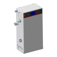
11.4 Control unit
The control unit is fastened to the frame with three screws. One
screw is at the back in the top centre, two screws are on the
bottom right and left in a void next to the cable connections.
Replacing the control unit
1. Switch off the main switch.
2. Unfasten the cover of the control unit.
3. Unfasten all cables from their connections and pull them out
of the glands.
4. Unscrew the two screws on the bottom right and left.
5. Lift the control unit off the screw in the top centre.
6. Hook the new control unit onto the screw in the top centre.
7. Fasten the bottom right and left screws again.
8. Reconnect the cables as described
9. Screw the cover back into place.
10. Switch on the main switch again.
11. If necessary, make a new set-up.
Warning
Only authorised service staff may carry out repairing.
Incorrect repairing may result in personal injury and
damage to property.
Switch off the system, and disconnect it from the
power supply before carrying out repairing.
Warning
Risk of gas poisoning due to escape of gas from a
damaged volume compensation bag.
Do not reach into the void behind the control unit.
Warning
Risk of burns due to the escape of chemicals from
faulty seals, leaky valves, hose connections and
lines.
Before starting work, put on protective clothing:
gloves, face mask, protective apron.
Flush the system before starting repairing, see
section 10.1 Flushing.

 Loading...