English (GB)
17
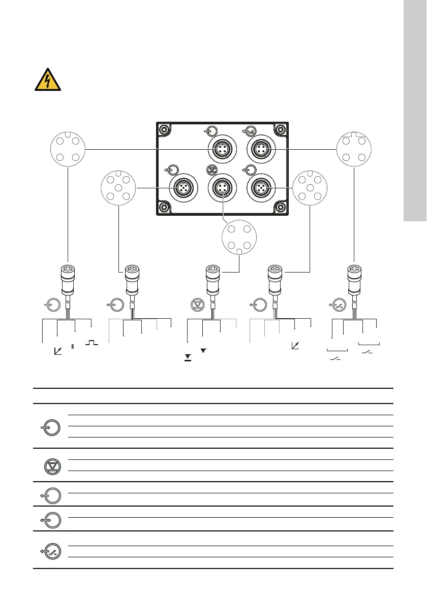
Signal connections
Fig. 12 Wiring diagram of the electrical connections
WARNING
Electric shock
Death or serious personal injury
- Electric circuits of external devices
connected to the pump inputs must be
separated from dangerous voltage by
means of double or reinforced
insulation!
TM06 7054 3818
2
1
3
4 4
4
5
3
22
1
2
3
4
1
2
1
3
Ź
2
1
GND
GND
12
34
12
34
12
5
34
34
12
12
5
34
4
5
3
1
GND
BUS
BUS
Symbol Function Pin assignment
1/brown 2/white 3/blue 4/black
Analog GND/(-) mA (+) mA
External stop GND X
Pulse GND X
1234
Low-level signal XGND
Empty signal XGND
1/brown 2/white 3/blue 4/black 5/yellow/green
Analog output (+) mA GND/(-) mA
1 2/brown 3/blue 4 5/black
GENIbus RS-485 A RS-485 B GND
1/brown 2/white 3/blue 4/black
Relay 1 XX
Relay 2 XX

 Loading...