English (GB)
44
8.4.4 Replacing the deaeration valve
This procedure requires a special tool kit. See
service kit catalogue:
• http://net.grundfos.com/qr/i/96488862_23
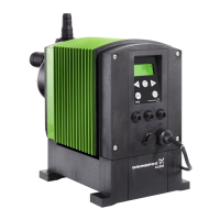
Fig. 46 Special tool kit
This section refers to fig. 44-46.
1. Put on the stipulated personal protective
equipment.
2. Switch off the power supply.
3. Make system pressureless.
4. Take suitable steps to ensure that the returning
liquid is safely collected.
5. Empty dosing head and flush it if necessary.
6. Dismantle deaeration line.
7. Manually unscrew deaeration screw (1).
– Do not use any tools, otherwise deaeration
valve parts can break.
– O-ring (1a) normally remains on the deaeration
screw.
– Valve ball (1b) normally remains in valve
housing (1c).
8. Use special tool (A) to unscrew valve housing
(1c) from double nipple (5a).
9. Remove hose nipple (1g) and flat gaskets (1f,
1h).
10. Use special tool (B) to unscrew double nipple
(5a).
Reassemble the deaeration valve with new parts as
follows:
11. Put in O-ring (5b).
12. Use special tool (B) to screw in the new double
nipple (5a) carefully with a torque wrench.
– Torque [Nm]: 3 (+/- 0.2).
13. Make sure that O-ring (1e) is seated correctly in
groove (1d).
14. Put flat gasket (1f) followed by hose nipple (1g)
and flat gasket (1h) onto valve housing (1c).
15. Use special tool (A) to screw in valve housing
(1c) into double nipple (5a) carefully with a torque
wrench.
– Torque [Nm]: 2 (+/- 0.2).
16. Make sure that O-ring (1a) is placed correctly on
deaeration screw (1).
17. Check that valve ball (1b) is correctly
pre-assembled in valve housing (1c).
18. Manually screw in deaeration screw (1).
19. Deaerate the dosing pump. See section
6.4 Deaerating the pump.
20. Observe the notes on commissioning in section
6. Startup.
8.4.5 Replacing the DLD sensor
This section refers to fig. 44-45.
1. Put on the stipulated personal protective
equipment.
2. Switch off the power supply.
3. Make system pressureless.
4. Take suitable steps to ensure that the returning
liquid is safely collected.
5. Empty dosing head and flush it if necessary.
6. Disconnect DLD signal connection. See fig. 14.
7. Carefully unscrew DLD sensor (9) with an
open-end spanner that fits accurately.
8. Replace gasket (9a).
9. Carefully screw in the new sensor into the dosing
head with an open-end spanner that fits
accurately.
– Torque [Nm]: 2 (+ 0.5).
10. Connect DLD signal connection.
11. Deaerate the dosing pump. See section
6.4 Deaerating the pump.
12. Observe the notes on commissioning in section
6. Startup.
8.4.6 Replacing the mains cable
All electrical connections must be carried out by a
qualified electrician in accordance with local
regulations.
1. Disconnect the pump from the power supply.
2. Unscrew safety screw (13a).
3. Replace mains cable (13) and gasket (13b).
4. Carefully screw in safety screw (13a) with a
torque wrench.
– Torque [Nm]: 0.4 (+/- 0.1)
The pump can start automatically when the power
supply is switched on.
The enclosure class (IP65 / Nema 4X) is only
guaranteed if plugs or protective caps are correctly
installed.
Do not manipulate mains plug or cable.
8.5 Resetting the service system
After performing the service, the service system
must be reset using the "Info > Reset service
system" function.
TM07 2852 4218
Pos. Description
A Special tool for valve housing
B Special tool for double nipple
CAUTION
Automatic startup
Minor or moderate personal injury
- Make sure the pump has been correctly
installed and is ready to be started
before you switch on the power supply.

 Loading...