English (GB)
30
7.5 Analog output
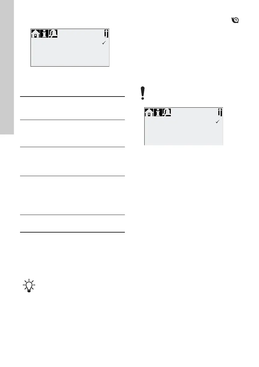
Fig. 34 Configure analog output
The analog output of the pump is parametrised in the
"Setup > Analog output" menu. The following
settings are possible:
* Output signal is based on motor speed and pump
status (target flow).
** Signal has same analog scaling as the current
analog input signal. See 7.4.3 Analog 0/4-20 mA.
Wiring diagram see section 5.3 Electrical
connection.
7.6 SlowMode
When the "SlowMode" function is enabled, the
pump slows down the suction stroke. The function is
enabled in the "Setup > SlowMode" menu and is
used to prevent cavitation in the following cases:
• for dosing media with a high viscosity
• for degassing dosing media
• for long inlet lines
• for large suction lift.
In the "Setup > SlowMode" menu, the speed of the
suction stroke can be reduced to 50 % or 25 %.
Fig. 35 SlowMode menu
TM06 7094 2916
Setting
Description of output
signal
Variant
FCM
AR
Output =
Input
Analog feedback signal
(not for master-slave
application). The analog
input signal is mapped
1:1 to the analog output.
XX
Actual
flow**
Current actual flow
• 0/4 mA = 0 %
• 20 mA = 100 %
see section 7.10 Flow
measurement
XX*
Backpre
ssure
Backpressure, measured
in the dosing head
• 0/4 mA = 0 bar
• 20 mA = Max.
operating pressure
see section 7.9
Pressure
monitoring
X
Bus
control
Enabled by command in
Bus control, see section
7.17 Bus communication
XX
In all operation modes, the analog output
has a range of 4-20 mA. Exception:
Operation mode 0-20 mA. Here, the
analog output range is 0-20 mA.
Output = Input
Actual flow
Backpressure
Bus control
❑
❑
❑
Analog out
Enabling the 'SlowMode' function reduces
the maximum dosing flow of the pump to
the set percentage value!
TM06 7094 2916
Off
SlowMode (50% max.)
SlowMode (25% max.)
❑
❑
SlowMode

 Loading...