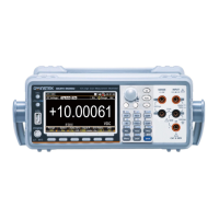
GDM-906X Series User Manual
222
An example below when optional accessory GTL-234 is
being employed. Likewise, first crossly link the pin 2
(TxD) to the pin 3 (RxD) and the pin 5 (GND) is the
necessary connection. Furthermore, crossly link the pin 7
(RTS) to pin 8 (CTS) for advanced function of GTL-234.
If more other cables are applied, the diagram of full
connections is illustrated as the following figure where the
pin 2 (TxD), pin 3 (RxD) as well as pin 5 (GND), as
mentioned previously, are necessary whilst the pin 4
(DTR), pin 6 (DSR), pin 7 (RTS) and pin 8 (CTS) are
optionally required depending on different cables with
varied functions to be used.
w ww. . com
information@itm.com1.800.561.8187

 Loading...