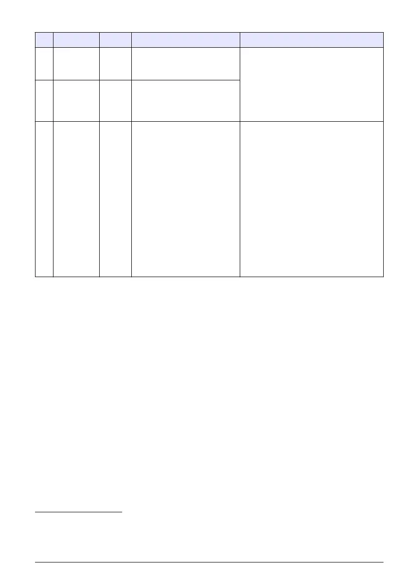
Table 1 Half cable wiring information
Pin Signal Color
1
Description Rating
1 +12 VDC
power
output
White Power supply positive output.
Only use with pin 2.
Battery power to the I/O module:
12 VDC nominal; Power supply to the
I/O module: 15 at 1.0 A maximum.
2 Common Blue Negative return of power
supply. When the power
supply is used, pin 2 is
connected to earth ground
2
.
3 Pulse input
or Analog
input
Orange This signal is a sample
collection trigger from the
flow logger (pulse or
4–20 mA) or a simple floating
(dry) contact closure.
Pulse input—Reacts to a positive
pulse with respect to pin 2. Termination
(pulled low): pin 2 through a series
1 kΩ resistor and 10 kΩ resistor. A
7.5 zener diode is in parallel with the
10 kΩ resistor as a protection device.
Analog input—Reacts to the analog
signal that enters pin 3 and returns on
pin 2. Input burden: 100 Ω plus 0.4 V;
Input current (internal limit): 40 to
50 mA maximum
3
Absolute maximum input: 0 to 15 VDC
with respect to pin 2.
Signal to make the input active: 5 to
15 V positive-going pulse
4
with respect
to pin 2, 50 millisecond minimum.
1
The wire color refers to the colors of multi-purpose cables (8528500 and 8528501).
2
All mains powered equipment that connects to the controller terminals must be NRTL listed.
3
Long-term operation in this state voids the warranty.
4
Source impedance of the driving signal must be less than 5 kΩ.
English 17

 Loading...


