9
4. PUMP OVERVIEW
All Hale Flex Series single stage booster pumps feature an integral gearbox and a self-adjusting me-
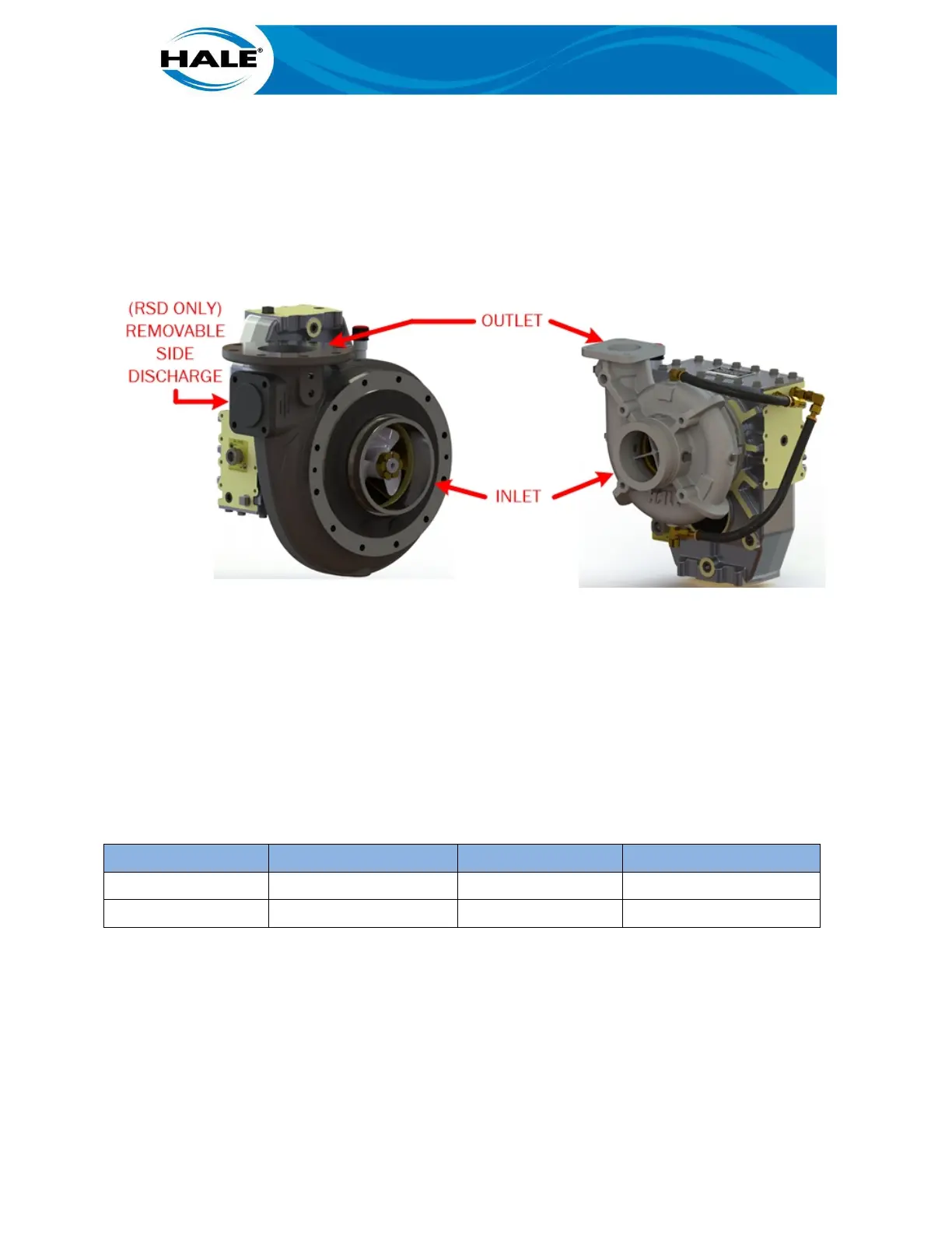
chanical seal and are volute style centrifugal pumps. The AP, CBP, and MBP pumps provide one inlet
and one outlet. The RSD provides an additional auxiliary side discharge (see Figure 4), typically used
to provide mounting for a TRV or an anode.
Figure 4. Hale Booster Pump Inlet And Outlet
Standard construction includes a bronze impeller and wrap around wear rings in an iron pump body.
All bronze construction is an option. The pumps are designed for water and need an external primer
(to evacuate air) to pump water from a static source. All Hale Flex Series single stage booster pumps
support outlet rotation, see Table 1 for the applicable drawing. The drawings are located on the flash
drive provided with the pump or on the Hale Products website (www.haleproducts.com).
Table 1. Hale Flex Series Single Stage Booster Pump Drawings
AP FSG–PL–01483 MBP FSG–PL–01486
CBP FSG–PL–01482 RSD FSG–PL–01487
Hale Flex Series single stage booster pumps are available for engine rotation or opposite engine ro-
tation to match the PTO (except MBP – ER only). Figure 5 shows both rotations and how to recognize
them. Verify the pump model matches the rotation of the PTO.