9
Before installing the appliance ensure that the chosen location is
suitable (Section 3.2) and that the requirements for flue position
(Section 3.3) and minimum clearances (Section 2.4) are satisfied.
These minimum clearances are essential to provide access for
servicing.
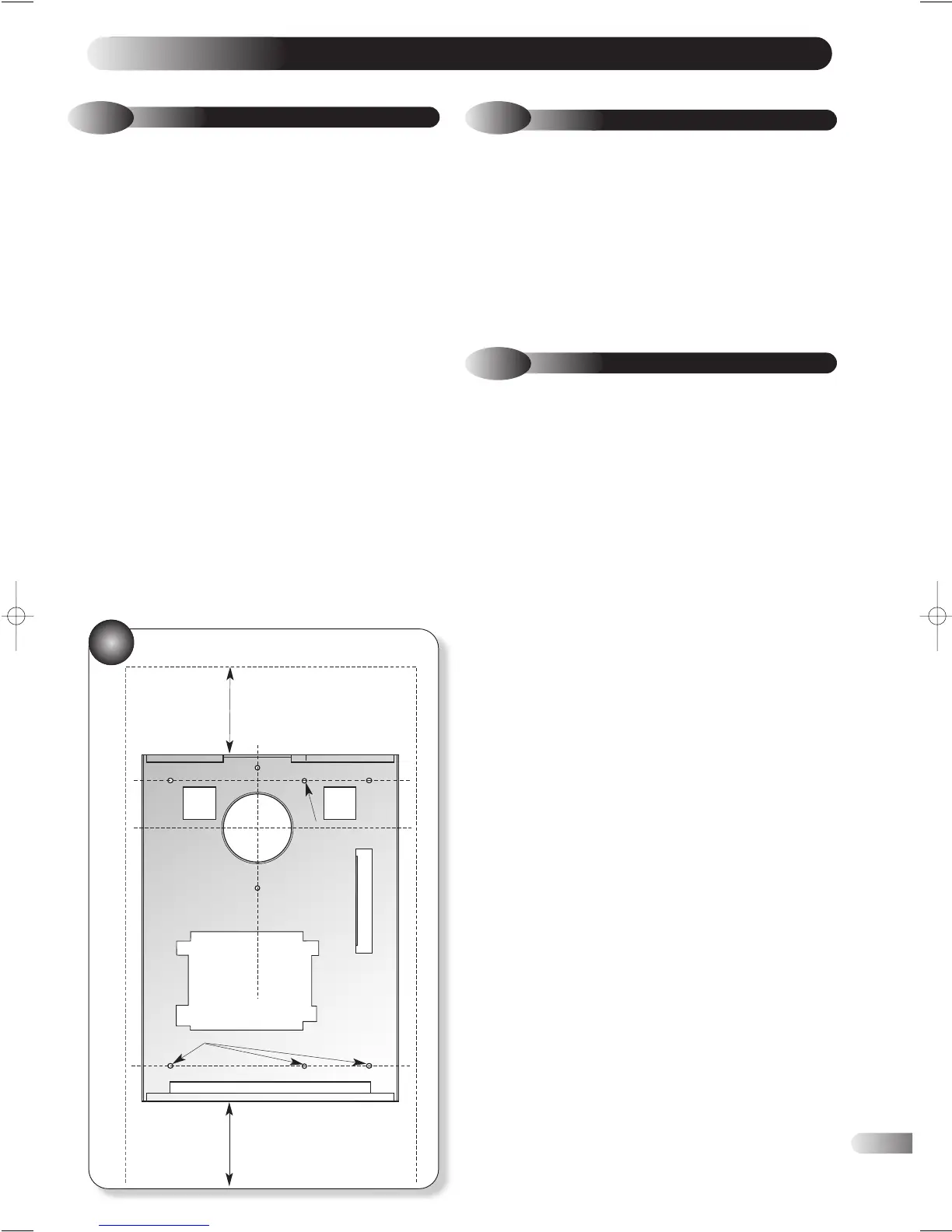
a) Remove the wall plate from the boiler and use it as a template
to mark the wall in the desired position (Fig 10). Ensure that
the centre line is level.
b) The appliance is supplied ready assembled for rear outlet flue
installations. For all other flue options proceed to section 4.2.2
a) Mark the position of the flue exit hole if it is a new installation,
or hold the wall plate over the existing flue hole in the wall.
b) Mark the position of the six wall plate fixing holes. Drill the
holes using a 8mm masonry drill and fit the wall plugs
provided.
If outside access to flue is possible:
c) Cut a hole through the wall of at least 100mm (4 in) diameter
to accept the flue/air duct.
d) Accurately measure the wall thickness. The standard flue
terminal is suitable for a wall thickness up to 330mm. For a
wall thickness in excess of 330mm see section 2.6 for optional
extension duct kits.
e) Secure the wall mounting plate in position.
f) Fit the external sealing ring (grey) to the terminal as shown in
Fig 11. Measure from the inside of the external sealing ring,
the wall thickness + 30mm (Fig 11) and cut the air/flue
duct appropriately, ensuring that the cut is square and free of
burrs or debris.
g) Push the air/flue duct terminal through the wall and the wall
plate from the outside.
If outside access to flue is NOT possible (eg. second or higher
storey):
h) The drilled hole should be at least 130mm (5ins) diameter to
allow for insertion of a wall liner (available as an optional
extra).
i) Once the air/flue duct has been cut to length (as above), fit
the outer (grey) seal to the air/flue duct. Feed the air/flue duct
through the hole from inside of the room and ensure that the
seal is seated properly on the outer wall.
j) Ensure that a full 30mm protrudes from the inside wall, drill
through the air duct and fixing to the wall plate using the 3
self tapping screws provided. Ensure the terminal is fitted
horizontally and the correct way up with the rain shield at the
top (see Figure 11)
k) Slide the two 10mm thick silicon sponge flue seals over the
protruding 30mm of the air/flue duct.
l) Remove both casing panels from the boiler, (six screws). Fig 11
m) Lift the boiler into position; the rear bottom edge of the boiler
onto the bottom return edge of the wall plate. Push the top of
the appliance back ensuring that the fan outlet (Fig12)
correctly engages into the flue terminal. Secure the boiler
using the two ‘over centre’ clamps on the top rear of the
appliance. Fig 11.
The appliance and standard flue kit is supplied in a single
cardboard carton. In addition various optional flue kits are
available as described in Section 2.6.
Open the carton in accordance with the packaging details.
Remove the appliance, the terminal flue kit and other components
and check the contents against the following list:
Boiler Package:
Boiler (assembled, incl. wall plate) Installation and User
Benchmark Logbook. instructions.
Front panel door.
Plastic bag containing: 6 x fixing screws.
6 x wall plugs. Outer wall sealing ring (grey)
Outer wall sealing ring (white) 2 x self tapping screws
2 x hinges. 4 x screws.
Standard flue terminal.
Manual Handling Note: During the appliance
installation it will be necessary to employ caution and
assistance whilst lifting as the appliance exceeds the
recommended weight for a one man lift.
Take care to avoid trip hazards, slippery or wet
surfaces.
INSTALLING THE APPLIANCE
4
4.2
PREPARING THE WALL / APPLIANCE
4.1
UNPACKING THE APPLIANCE
16
10
WALL MOUNTING PLATE
4.2.1
REAR OUTLET FLUE
WALL FIXING HOLES
CENTRE LINE OF BOILER FLUE
WALL FIXING HOLES
50MM* CLEARANCE
ABOVE CASE FOR REAR FLUE
100 MM
CLEARANCE
BELOW CASE
*200mm clearance needed for
side flue application