EasyManua.ls Logo

Halstead Hero 30 - Combustion Chamber Insulation; Front Panel Insulation; Side Panel Insulation; 8 Internal Wiring Diagrams

Halstead Hero 30
28 pages
Print Icon
To Next Page IconTo Next Page
To Previous Page IconTo Previous Page
Loading...
FLOW CHART 1: START/POWER UP FAULT FINDING
The design of the appliance is such that the combustion chamber
insulation should not require replacement unless mechanically
damaged. It is recommended that a protective mask is worn when
changing or handling insulation material.
COMBUSTION CHAMBER
INSULATION
7.10
7.10.1
FRONT PANEL INSULATION
a) Carry out procedures detailed in section 7.6 points a) to c)
inclusive.
b) Remove the insulation panel from the combustion chamber
front panel and replace, ensuring location behind the bottom
holding tab.
c) Re-assemble the appliance in reverse order.
7.10.2
SIDE PANEL INSULATION
a) Carry out procedures detailed in section 7.6 points a) to e)
inclusive.
b) Replace the insulation panel (s) and re-assemble the appliance
in reverse order taking note of point g) of section 7.6.
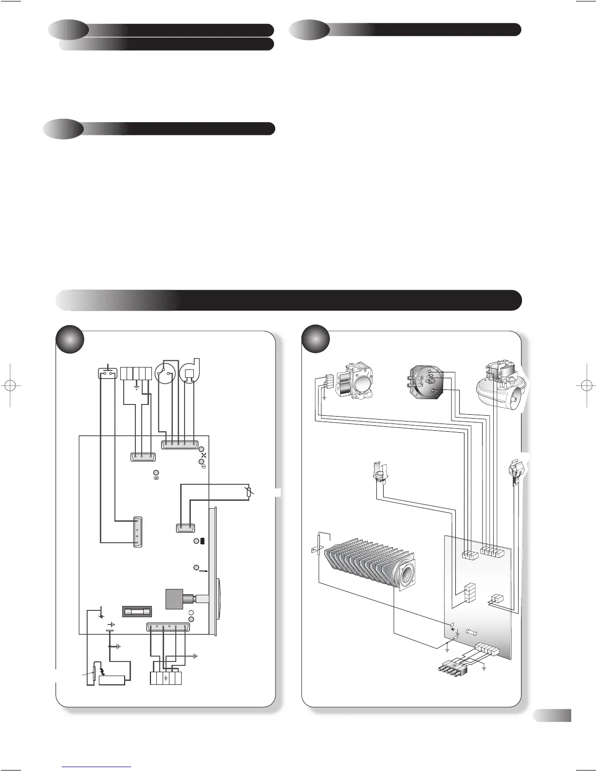
INTERNAL WIRING DIAGRAMS
8
Blue
Blue
Blue
Brown
Brown
Brown
Brown
Grey
Yellow
Red
Orange
Orange
Yellow
Red
Natural
L1 L2 N L3
Burner
HT and flame
sense electrode
Thermistor
Fan
230V AC
Air pressure
switch
Overheat
thermostat
HT
Fuse
Gas valve
White
White
White
Terminal block
Stevilo 6 way (X8)
Stevilo 2 way (X3)
Stevilo 4 way (X15)
Stevilo 3 way (X2)
Stevilo 5 way (X1)
Neon L3
Neon L2
Neon L6
NeonL4
Neon L5
Neon L1
Gas valve
Overheat thermostat
Thermistor
Terminal block
Electrode
Burner
Air pressure switch Fan
PCB
L1
L2
L
3
N
R
ed
Y
e
l
lo
w
B
r
ow
n
Bl
u
e
Whi
t
e
N
e
u
t
ra
l
Oran
ge
Ora
nge
B
lue
Br
o
w
n
B
r
o
w
n
Red
Ye
llow
Gre
y
Brown
Blue
White
White
23
37
38
Hero 1/03 TO PRINT 8/5/03 10:45 am Page 23

Table of Contents

Related product manuals