ROUTINE SERVICING
6
To ensure the continued efficient operation of the appliance, it is
highly recommended that regular servicing is carried out. As a
general guide a service on an annual basis should be adequate.
It is law that any service work must be carried out by a competent
person such as a CORGI registered engineer.
6.1
If the service engineer has suitable equipment for analysing flue
gas products it is possible to check the current operation of the
appliance prior to the service.
The appliance incorporates a flue gas sampling point on the air
pressure switch sensing tube, located at the top right hand side of
the appliance (Fig 31).
a) Open the hinged front door (if fitted) and remove the 2 screws
securing the right hand side casing panel. Slide forwards to
disengage.
b) Remove the plastic cap from the lower sensing tube ‘T’-piece
(negative side of the switch) and connect a suitable sensing
tube from the analyser. Check CO
2 value and compare with
figure stated in section 2.4.
c) Replace the plastic cap after use.
CHECKING THE OPERATION OF
THE APPLIANCE
6.2
a) Isolate the mains electrical supply.
b) If fitted, remove the hinged front door from the appliance by
removing the 2 screws from each hinge (Fig 30).
c) Remove the 2 screws securing the right hand side casing
panel and slide forwards to disengage.
d) Isolate the gas supply at the isolation valve situated at the
bottom right hand side of the appliance.
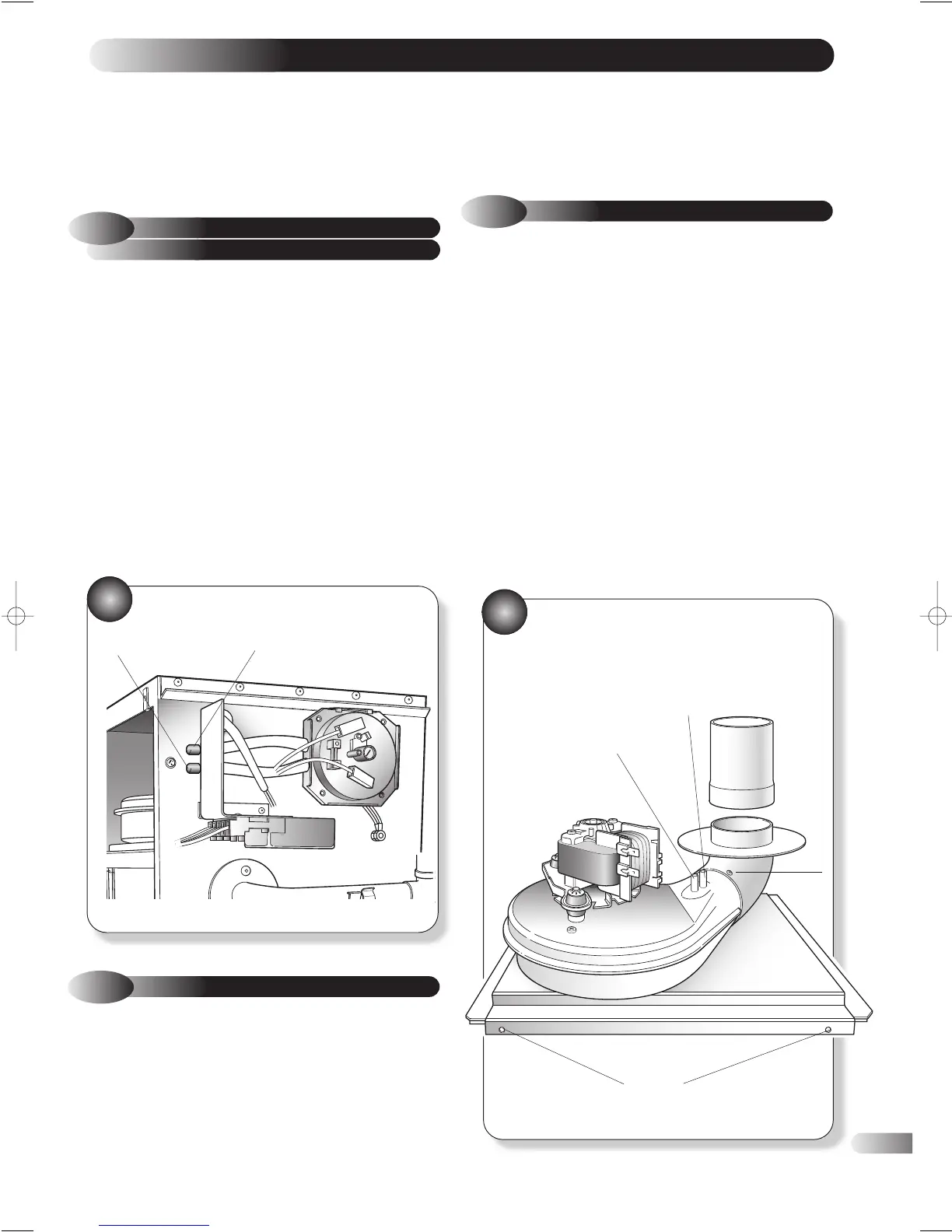
COMMENCING WITH SERVICING
6.3
a) Disconnect the two electrical wires from the fan motor.
b) Disconnect the air pressure switch sensing tubes from the fan
noting that the tube furthest from the fan outlet is connected to
the positive (+) side of the air pressure switch. (Fig 32)
c) If a rear outlet flue is fitted simply withdraw the fan assembly
from the appliance and remove the fan outlet to flue
connector. (Fig 12)
d) If a top outlet is used, remove the screw securing the fan outlet
elbow and disengage the elbow whilst withdrawing the fan
assembly from the appliance. (Fig 32)
e) Inspect the fan assembly (especially the impeller and the flow
sensing venturi in the outlet) for dirt, damage or signs of wear.
If necessary clean the components using a soft brush or
vacuum cleaner. Spin the impeller and check for free rotation
without noise and without imbalance. If there are any signs of
damage, replace the fan in accordance with section 7.5.
FAN ASSEMBLY
SENSING TUBES
31
e) Remove the 4 screws securing the left hand side casing panel
and slide forwards to disengage.
f) Service the appliance by following the procedure detailed
below:
17
32
REMOVE ELBOW ADAPTOR
•
•
(+) SIGNAL
19
FLUE SAMPLING
POINT
•
•
+ PRESSURE
POINT
- PRESSURE
POINT
•
FIXING
SCREW
FLUE HOOD
SECURING SCREWS
•
•