2.6
AIR/FLUE DUCT SPECIFICATION
Variations upon these illustrations may be used providing that the
following rules are strictly obeyed:
a) Determine the type of flue applications and chose the appropriate
flue option requirements.
b) Ensure that the maximum allowable flue length of the flue
system doesn’t exceed:
HERO 30 - 75 HERO 90
a. 4000 mm vertical a. 3200 mm vertical
b. 3000 mm horizontal b. 2000 mm horizontal
c) The standard terminal must always be fitted horizontally. The
vertical terminal must always be used if a vertical roof outlet is
required.
d) The flue must only terminate in a horizontal or vertical
position. However 90° flue elbows may be used to drop the
height of the flue system by 500 mm.
e) For side outlet horizontal or vertical flue applications the flue
system must use either a flanged elbow or a flanged socket at
the entry/exit to the appliance.
f) All joints must be correctly made and secured in accordance
with the installation instructions.
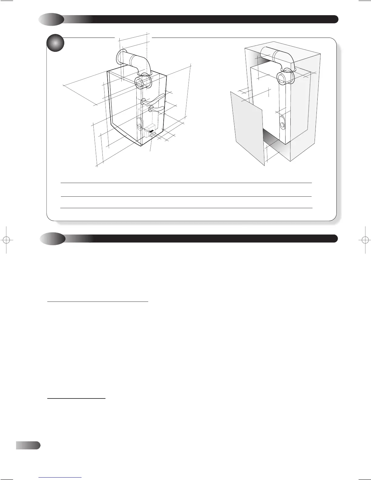
Installation instructions for installing the appliance with a standard
flue (Fig 2) are included in the main text of these instructions
(section 4.5). Additional instructions for flue systems incorporating
vertical applications are given in the Halstead Flue Guide and
User Instructions as part of the flue kit.
The appliance is supplied complete with a standard flue terminal
which is suitable for a wall thickness up to 330mm. For wall
thicknesses in excess of 330mm use Rear Flue extension duct
(955081). Dimension as shown in Fig. 2a)
The following additional concentric flue kits are also available as
optional extras.
For side outlet horizontal (or raised) applications:
Top Outlet HORIZONTAL Connection Kit (955080) is
available as an optional extra. The kit comprises internal
connector elbow assembly, 90 degree flanged elbow, vertical flue
turret socket, telescopic flue outer and inner seal.
Extension duct (955065): each extension duct extends the
flue length by up-to 767 mm.
90° Extension Elbow (954011): This is an in-line elbow and
mechanically different from the flanged elbow, but has the same
equivalent length of 767 mm.
45° Extension Elbow (954010): Allows an additional bend in
the flue and has an equivalent length of 384 mm.
For ver
tical flue applications:
Top Outlet VERTICAL Connection kit ( 955082) is available
as an optional extra (For use with vertical flue kit 988378)
comprising internal connector elbow assembly and 425mm flue pipe.
Vertical Flue Kit (988378): For vertical roof terminal
applications. The kit comprises of vertical terminal, pitched roof
flashing, reducer sockets and vertical turret.
These optional flue kits may be used to produce an extensive
range of flue options.
1
2.5
OVERALL DIMENSIONS AND MINIMUM CLEARANCES
2
GAS COCK
•
•
•
•
•
•
•
•
•
•
•
•
•
•
•
•
•
•
•
•
•
•
•
•
•
•
•
•
•
HERO A B C D E F G H I J K L M N O P Q R
30-60 200 6 6 100 300 325 275 432 105 353 249 285 122 197 107 400 540 104
75/90 200 6 6 100 300 405 355 432 105 353 249 365 162 277 107 400 540 104
•
•
•
•
P
Q
•
•
R
F
G
I
J
K
H
M
L
O
N
A
E
D
B
C