11
4.2.2
TOP OUTLET FLUE
a) Having chosen the desired location for the boiler, for all top
outlet flue connections the appropriate (optional extra) kit(s) as
detailed in section 2.6 will be required.
b) The centre line for the flue system is slightly off-centre and
indicated on the wall plate with a notch. Draw a vertical line
from the notch as shown in Fig 14.
c) The Horizontal turret centre line for side outlet flues is
100mm above the wall plate, extend the line horizontally until
reaching the sidewall face, and then draw the position of the
air/flue duct hole. Cut a hole through the wall of at least
95mm (4 in) diameter to accept the flue/air duct. Note ~ if
access to the hole from outside is not possible the hole should
be at least 130mm (5 in) diameter to allow for insertion of the
wall liner (available as an optional extra).
d) For Vertical Flue Outlet, extend the line vertically until
reaching the ceiling/roof. The centre line of the flue from the
wall is 109 mm. Cut a hole through the ceiling / roof of at
least 100mm (4 in) diameter to accept the flue/air duct.
e) For Offset flue combinations and additional elbows
calculate from the dimensional details in section 2.5 And 2.6
Where the flue should be positioned. Make the necessary hole
in the wall / ceiling / roof.
f) Mark the position of the six wall plate fixing holes. Drill the
holes using a 8mm masonry drill and fit the wall plugs
provided.
g) Secure the wall mounting plate to the wall using the screws
provided.
4.3
AIR/FLUE DUCT
INSTALLATION (HORIZONTAL)
Note~ If the wall thickness is less than 800mm (31 in) the air/flue
duct may be fitted without access to the external wall providing
that the optional wall liner is used. (This is necessary to seal any
cavity and to allow the sealing ring to pass through from inside
but still open and provide an adequate seal). The wall liner has a
tube diameter of 130mm with a wall thickness of 0.8mm.
All flue duct lengths in excess of 1.5m (59 in) require
at least one support bracket in the middle of the duct.
(Available as optional extra Part No: 840516)
14
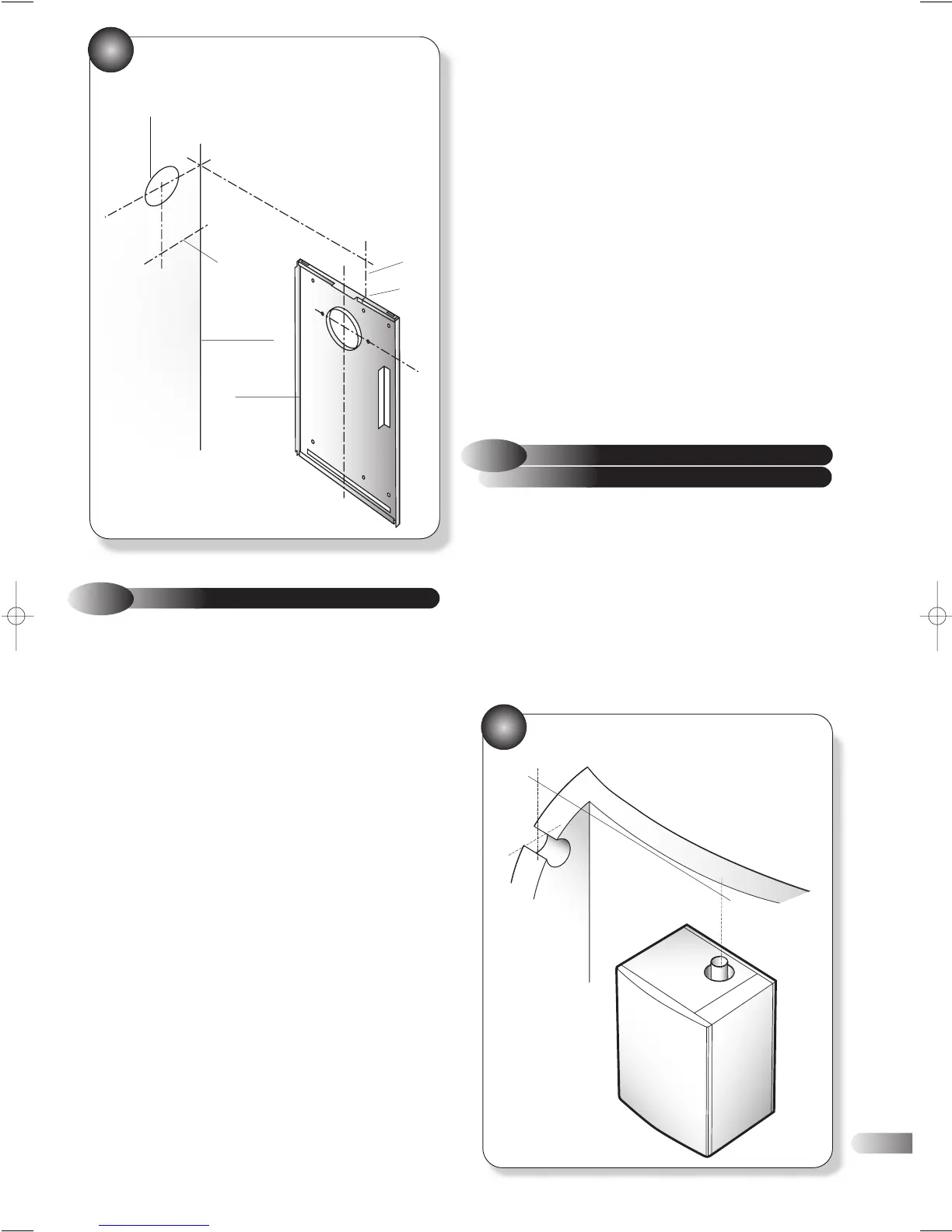
MARKING THE POSITION OF A
SIDE FLUE
17
15
MEASURING THE EXACT FLUE LENGTH
h) Remove both casing panels from the boiler, (6 screws).
i) Lift the boiler into position; the rear bottom edge of the boiler
locates onto the bottom return edge of the wall plate. Push the
top of the appliance back. Secure the boiler using the two
‘over centre’ clamps on the top rear of the appliance. (Fig 11)
j) Remove the fan assembly from the appliance (Refer to section
7.5).
k) Remove the appliance top outlet cover plate and relocate onto
the rear of the appliance to blank the rear outlet opening.
l) With the fan removed from the fan plate, reposition and
secure the fan so that the outlet is directed to the right hand
side of the appliance. Refit the fan assembly (Refer to section
7.5).
m) Fit and secure the 60mm Ø elbow (Fig 16) and all other
relevant boiler components relating to the flue kit(s) option
chosen (Full instructions included in the kits).
n) Ensure the flue duct restrictor ring is in accordance with the
the technical specifications in section 2. and is correctly fitted.
(Fig13)
•
95mm
•
•
•
•
•
•
•
•
109mm
CORNER
OF WALL
WALL
MOUNTING
PLATE
POSITION OF
DUCT HOLE
•
•
TOTAL FLUE LENGTH FROM
FLUE OUTLET CENTRE TO
OUTSIDE WALL FACE:
=LENGTH L
L
WALL
NOTCH