COMMISSIONING AND TESTING
5
5.1
OPEN VENTED WATER SYSTEMS
Checks to ensure electrical safety should be carried out by a
competent person.
The whole of the gas installation should be inspected, checked for
soundness and purged in accordance with the recommendations
of BS 6891.
Before carrying out the following procedures ensure that the main
inner seal casing panel is correctly fitted.
a) Fill and flush the system with all valves open. Refill the system
and check for water leakage. Vent the system including all
radiators and ensure the pump isolating valves, the bypass
and motorised valves (if fitted) are fully open.
b) Turn on the gas supply at the appliance service isolation
valve.
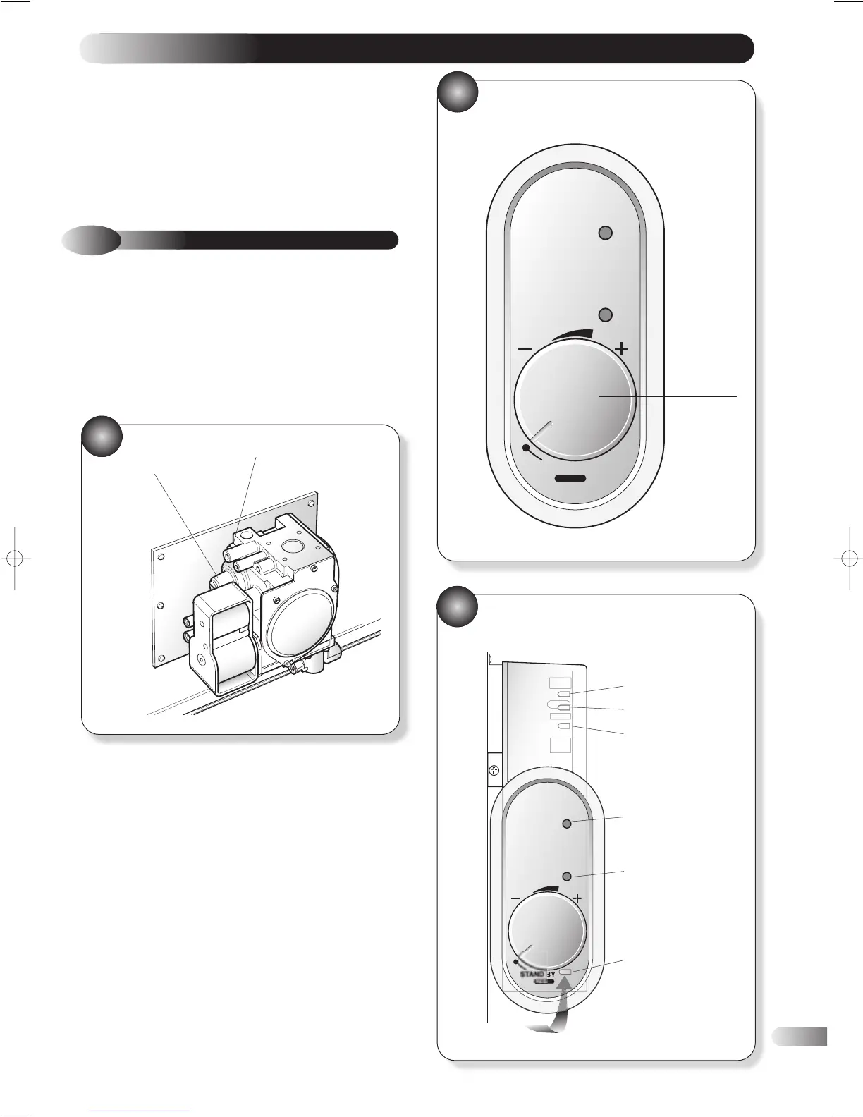
c) Slacken the burner pressure test point screw and connect a
suitable test pressure gauge. (see fig 27).
d) Ensure that all external controls (e.g timer, room thermostat
and cylinder thermostat where fitted) are turned to maximum.
e) Turn on the electrical supply and check the pump is working
and water is circulating through the system.
f) Turn the appliance control thermostat device fully clockwise to
the maximum setting. After a maximum of 10 seconds the
appliance should light. This is indicated by illumination of the
burner ‘on’ neon (see fig 28).
g) If the burner fails to light turn the boiler thermostat fully anti-
clockwise to the reset position and repeat (f).
h) Allow the appliance to operate for 10 minutes and check that
the burner pressure is in accordance with the performance
data detailed in section 2.2. If the burner pressure is incorrect,
check that an inlet pressure of between 18 - 25 mbar (7 – 10
in wg) is maintained at the gas meter when all appliances on
the system are operating.(For 40P and 60P inlet pressure of
37 mbar)
GAS VALVE
CONTROL BEZEL