e) A compartment used to enclose the appliance MUST be designed
and constructed specifically for this purpose. An existing
cupboard, or compartment, may be used provided it is modified
accordingly. BS 6798 gives details of the essential features of
cupboard / compartment design, including airing cupboards.
f) Where installations will be in unusual locations, special
procedures may be necessary. BS 6798 gives detailed
guidance on this aspect.
Detailed recommendations for flue installations are given in BS 5440:
1 and :2. The following notes are for general guidance:
a) The boiler MUST be installed so that the terminal is exposed to
the external air.
b) It is important that the position of the terminal allows free
passage of air across it at all times.
c) It is ESSENTIAL TO ENSURE that products of combustion
discharging from the terminal cannot re-enter the building, or
any other adjacent building, through ventilators, windows,
doors, other sources of natural air infiltration, or forced
ventilation / air conditioning.
d) If the terminal discharges into the pathway or passageway
check that combustion products will not cause nuisance and
that the terminal will not obstruct the passageway.
e) Where the lowest part of terminal is fitted less than 2m (78ins)
above the ground, above a balcony or above a flat roof to
which people have access, the terminal MUST be protected by
a purpose designed terminal guard (optional extra; Part- No.
951505)
f) The air inlet / flue outlet duct MUST NOT be closer than
25mm (1in) to combustible material.
g) In certain weather conditions the terminal may emit a plume
of steam. This is normal but positi
ons where this could cause a
nuisance should be avoided.
Detailed recommendations for air supply are given in BS 5440:2.
The following notes are for general guidance.
a) It is not necessary to have a purpose provided air vent in the
room or internal space in which the appliance is installed.
b) If the boiler is to be installed in a wall cupboard permanent air
vents are required for cooling purposes in the cupboard at both
high and low levels. Both air vents must communicate with either
the same internal room / space or to be on the same wall to
external air. Each air vent communicating with another room or
internal space must have a minimum effective area of:
5625 mm
2
(Top and Bottom).
3.5
GAS SUPPLY
a) The Gas Supplier should be consulted at the installation planning
stage in order to establish the availability of an adequate supply
of gas.
b) The appliance is for use only on G 20 natural gas (HERO 40
and 60 are also available for LPG).
c) An existing service pipe MUST NOT be used without prior
consultation with the Gas Supplier.
d) A gas meter can only be connected by the Gas Supplier or
by their contractor.
e) An existing meter and / or pipework should be of sufficient size
to carry the maximum boiler input plus the demand of any other
installed appliances (gas consumption under Section 2) and in
accordance with BS 6891. A minimum of 22mm dia.
pipework is required to within 1metre of the
appliance gas cock.
f) The governor at the meter shall provide a constant working outlet
pressure of between 18 – 25 mbar ( 37 mbar for LPG) when all
appliances on the system are running. If the gas pressure is
outside that band the Gas Supplier has to be consulted.
g) The gas supply line must be purged. WARNING: Before
purging open all doors and windows, also extinguish any
cigarettes, pipes and any other naked lights.
h) The complete installation must be tested for gas soundness.
3.6
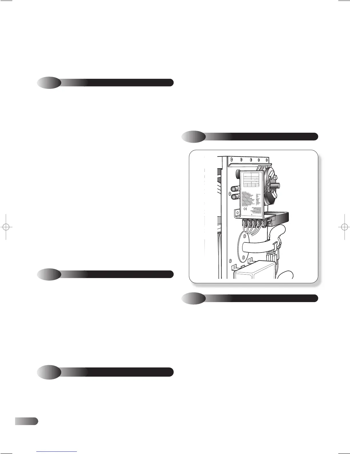
DATA LABEL
3.4
VENTILATION REQUIREMENTS
3.7
ELECTRICAL SUPPLY
The mains supply required is 230 V – 50 Hz fused at 3 A, via a
fused double pole isolator with a contact separation of at least 3 mm
in both poles. This should be a permanent connection to the fixed
wiring of the system.
There must be only one common isolator for the boiler and its control
system, and it must be provide complete electrical isolation.
The power supply cable to the appliance should be at least 0.75
2mm (24 x 0.2 mm) PVC heat resistant, as specified in table 16 of
BS6500.
All external wiring to the boiler must be in accordance with the latest
I.E.E. Wiring Regulations, and any other local regulations which
apply.
The appliance must be earthed. .
In the event of any electrical fault after installation of the appliance,
preliminary electrical system checks must be carried out, i.e. Earth
Continuity, Short Circuit, Polarity and Resistance to earth.
All fuses must be ASTA approved to BS1362.
6
3.3
FLUE TERMINAL POSITION