21
REPLACEMENT OF PARTS
7
Before commencing any replacement operation, ISOLATE the
mains electrical supply.
Open the hinged front door panel to expose the two inner casing
panels.
Undo the two screws securing the right hand side inner casing
panel and pull forwards to remove.
TURN OFF THE GAS SUPPLY AT THE MAIN SERVICE COCK.
Following the completion of any replacement operation, the
appliance shall be commissioned in accordance with Section 5 of
these instructions.
7.1
OVERHEAT CUT OFF DEVICE
a) Disconnect the two electrical connections at the device.
b) Unclip the device from the upper flow pipe.
c) Remove device from pipe clip to replace.
d) Clip onto the flow (upper) pipe ensuring good contact of
device.
e) Reconnect the electrical wires (polarity is not important) and
re-assemble appliance in reverse order.
FLOW TEMPERATURE
a) Disconnect the twin wire plug from the device.
b) Unclip the device from the flow (upper) pipe.
c) Replace the device and re-clip to the flow upper pipe ensuring
good contact.
d) Replace the twin wire plug and re-assemble appliance in
reverse order.
SENSING DEVICE
7.2
7.3
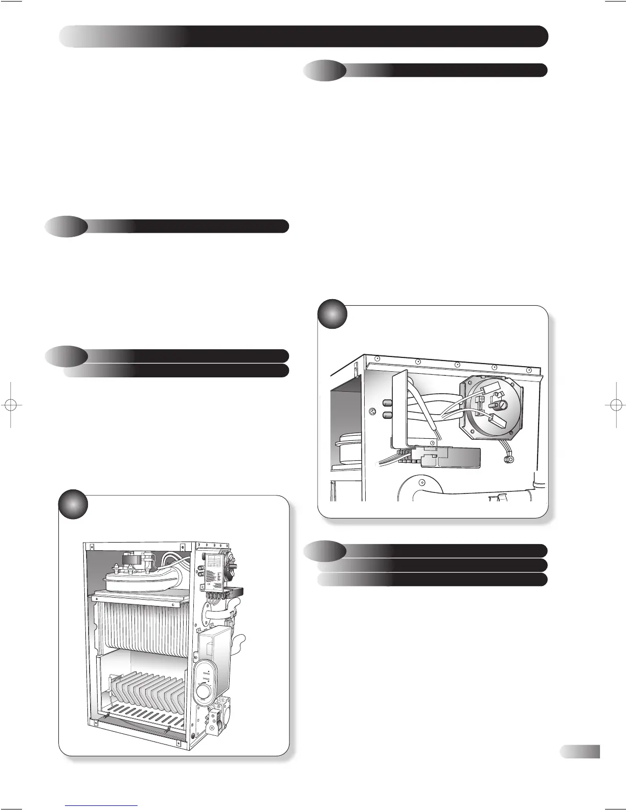
AIR PRESSURE SWITCH
a) Disconnect the 3 electrical connections from the switch.
b) Disconnect the sensing tubes from the switch.
c) Unclip the air pressure switch from the mounting bracket by
pulling the bottom of the switch away from the boiler body.
Replace the switch and refer to Fig 34 and section 8 (wiring
diagram).
d) Reconnect the sensing tubes. The upper most tube being
connected to the positive (+) side of the switch.
e) Reconnect the electrical wires to the correct terminal on the
switch.
Red = 1 = N/C
Yellow = 2 = N/O
Grey = 3 = Common
f) Re-assemble appliance in reverse order.
BOILER SIDE
33
SENSING TUBES
34
a) Remove the single screw securing the control box to the
appliance and pull forwards to disengage.
b) Disconnect the ignition lead, the earth and the four wiring
harness plugs from the board.
c) Unclip the control panel and remove the control device from
the box.
d) Replace the control box and re-assemble in reverse order.
Note ~ For all other component replacement detailed
in sections 7.4 to 7.10, remove the main inner casing
panel secured by the four screws. Pull forward to
disengage.
7.4
ELECTRONIC DIAGNOSTIC
AND IGNITION SEQUENCE
CONTROL BOARD