24
FAULT FINDING
9
Before proceeding through this fault finding, ensure all connections
to the electronic circuit board and the mains supply plug (Refer to
Section 4.6) are correctly fitted.
Carry out preliminary electrical safety checks in accordance with
‘Regulations for Electrical Installations’.
a) Position the temperature control to STANDBY.
b) Turn ON external gas and electricity supplies.
c) Ensure there is 230V at the permanent live ‘L1’ on the
installation terminal block.
d) Ensure there is 230V at the switched live ’L3’ on the
installation terminal. This is the feed from the external controls,
they should be set to ON or MAXIMUM. A link between
terminals ‘L1’ and ‘L3’ will simulate the external controls being
ON.
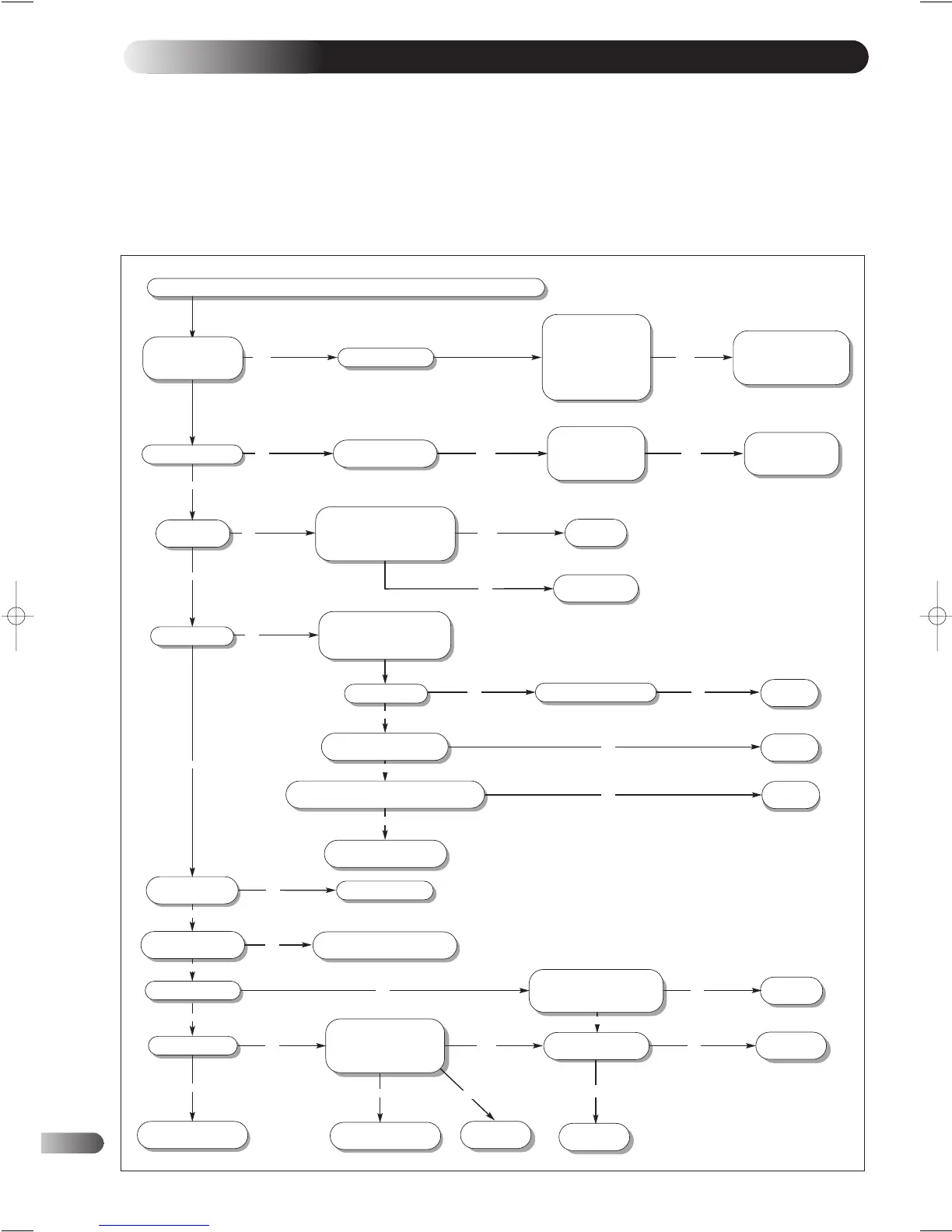
Ensure that external controls are calling for heat and circuit water is well below set flow temperature
Flame failure occurred
Is neon 3 (fan) lit?
Is the fan running?
Is neon 1 (stand-by) lit?
Check there is 230V
ac between L1 and N
check gas pipe is open
and purged
check spark lead is
properly connected
check electrode has the
correct distance (Fig.36)
Check power supply
and terminal
connections are
correct.
Isolate the electrical supply and
check the thermistor's resistance.
The resistance should be
between 14 k - 2.5 Kohms
Faulty PCB.
Replace
Faulty Thermistor.
Replace
Is there 230V ac on the fan?
Isolate the electrical supply
and gain access to the fan
Switch on electrical supply
Faulty fan.
Replace
Faulty PCB.
Replace
Faulty APS.
Replace
Check for 230V ac between
N and contact on APS
Measure APS pressure diff. Is the the pressure
below the quoted pressure on the housing?
Check flue system and
restrictor are correctly fitted
Does sparking take
place? (audible)
Does the spark arc
across the burner?
Does the burner light?
Is neon 4 (flame) lit?
Check electrode is correctly fitted
and spark lead is connected
Check Polarity of mains;
check electrode is correctly
fitted and spark lead is
connected
Check for 230V ac across N
and brown and between N and
blue on 3 way connector PCB
Check gas valve harness
for continuity
RESET boiler by turning
temperature control to
OFF, waiting 30 sec and
then ON again.
Check on-board fuse
is not broken (pump
fault)
Faulty PCB.
Replace
Faulty harness.
Replace
Is neon 2
(demand on) lit?
Faulty PCB. Replace
YES
YES
YES
YES
YES
YES
YES
YES
YES
YES
YES
YES
YES
YES
NO
NO
NO
NO
NO
NO
NO
NO
NO
NO
NO
YESNO
NO
NO
Boiler’s ignition
sequence is correct
Repair/Replace electrode
& spark lead assembly
Faulty PCB.
Replace
Faulty gas valve.
Replace
YES
NO
YES
YES
Has neon ' L6' on the
PCB (Fig. 37)
[section 8] lit?
YES
Hero 1/03 TO PRINT 8/5/03 10:45 am Page 24