a) Carry out the procedures detailed in section 7.6 points a)
to d) inclusive.
b) Remove the two screws which retain the electrode bracket to
the burner cradle.
c) Replace the electrode checking that the alignment and spark
gap is correct (Refer to Fig 36 Showing the correct position of
the electrode & the dimension of spark gap).
d) Re-assemble the appliance in reverse order taking note of
point g) of section 7.6.
7.8
GAS VALVE
a) Carry out the procedures detailed in section 7.6 a) to d)
inclusive.
b) Remove the 4, M3 allen screws which retain the gas service
isolation device to the gas valve.
c) Pull off the 4 wire plug from the gas valve.
d) From inside the boiler, remove the 3 x M3 allen screws which
retain the valve to the appliance and remove valve.
e) Replace the gas valve checking that the inlet and outlet ‘O’
ring seals of the valve are in good condition. (Replace if
necessary)
f) Re-assemble the appliance in reverse order taking note of
point g) of section 7.6.
7.7
INJECTOR
a) Carry out the procedures detailed in section 7.6 a) to d)
inclusive.
b) Remove the injector and replace. Re-assemble appliance in
reverse order taking note of point g) of section 7.6.
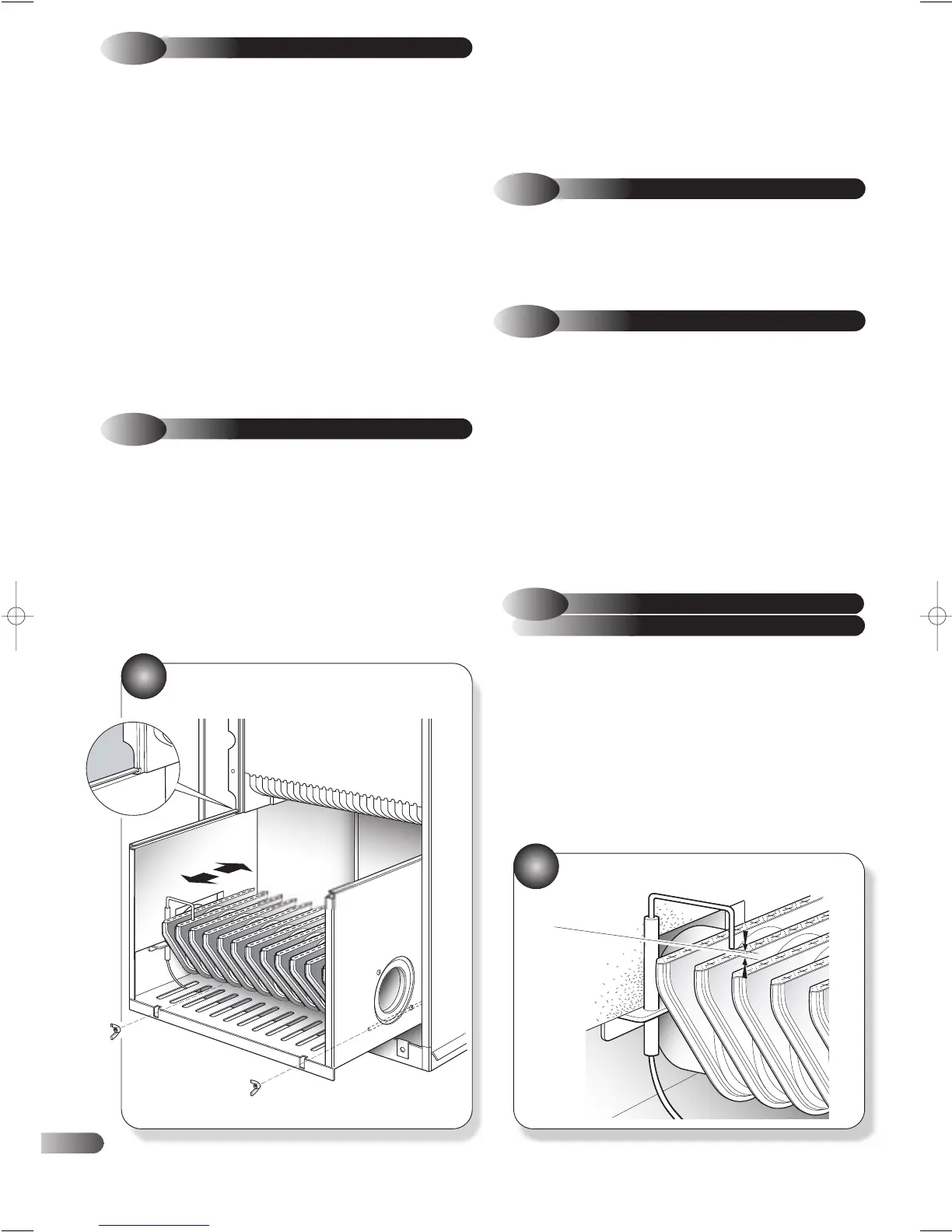
IGNITION / FLAME
SENSING ELECTRODE
7.9
g) Replace the burner and re-assemble appliance in reverse
order. Ensure that the burner cradle assembly is correctly
located on the top runners and the tie rods. (Refer to Fig 35
Showing burner location on the runners and tie rods ) Push
firmly to the rear of the appliance and ensure correct
engagement of the insulation panels.
7.6
MAIN BURNER
a) See note after section 7.4.
b) Remove the four screws and two wing nuts securing the
combustion chamber front panel.
c) Lift slightly the fan plate assemble and withdraw the panel.
d) Withdraw the burner assembly cradle from the appliance and
detach the ignition lead and earth connection.
e) Carefully remove the insulation board from the cradle.
f) Remove the two M3 allen screws at the injector end and the
nut at the opposite end of the burner and remove burner from
cradle.
BURNER REMOVAL
ELECTRODE ALIGNMENT
36
7.5
FAN ASSEMBLY
a) See note after section 7.4.
b) Disconnect the live and neutral wires from the fan motor.
c) Disconnect the air pressure switch sensing tubes from the fan
noting that the tube furthest from the fan outlet is connected to
the positive (+) side of the air pressure switch. (Refer to
Fig 12)
d) If a rear outlet flue is fitted simply withdraw the fan assembly
from the appliance and remove the fan outlet to flue
connector.
e) If a top outlet is used, remove the screw securing the fan outlet
elbow and disengage the elbow whilst withdrawing the fan
assembly from the appliance. (Refer to Fig 32)
f) Remove the fan from the fan plate (4 screws).
g) Replace the fan and re-assemble the appliance in reverse
order ensuring correct orientation of the fan, correct engaging
of fan plate assembly into the rear locating slots and correct
sensing tube positions (see point c).
35
SPARK GAP
2.5mm TO 4mm
22