ELECTRICAL CONNECTIONS
22
4.6
This appliance must have a permanent mains supply and be
earthed.
Use standard colours for the supply:
Brown = Live (L)
Blue = Neutral (N)
Green/Yellow = Earth (E)
Note~ It is highly recommended that this appliance is connected
to an external control (timer / programmer) as part of the
Approved Code of Practice and guidance Safety and Good
Practice Guide 302.
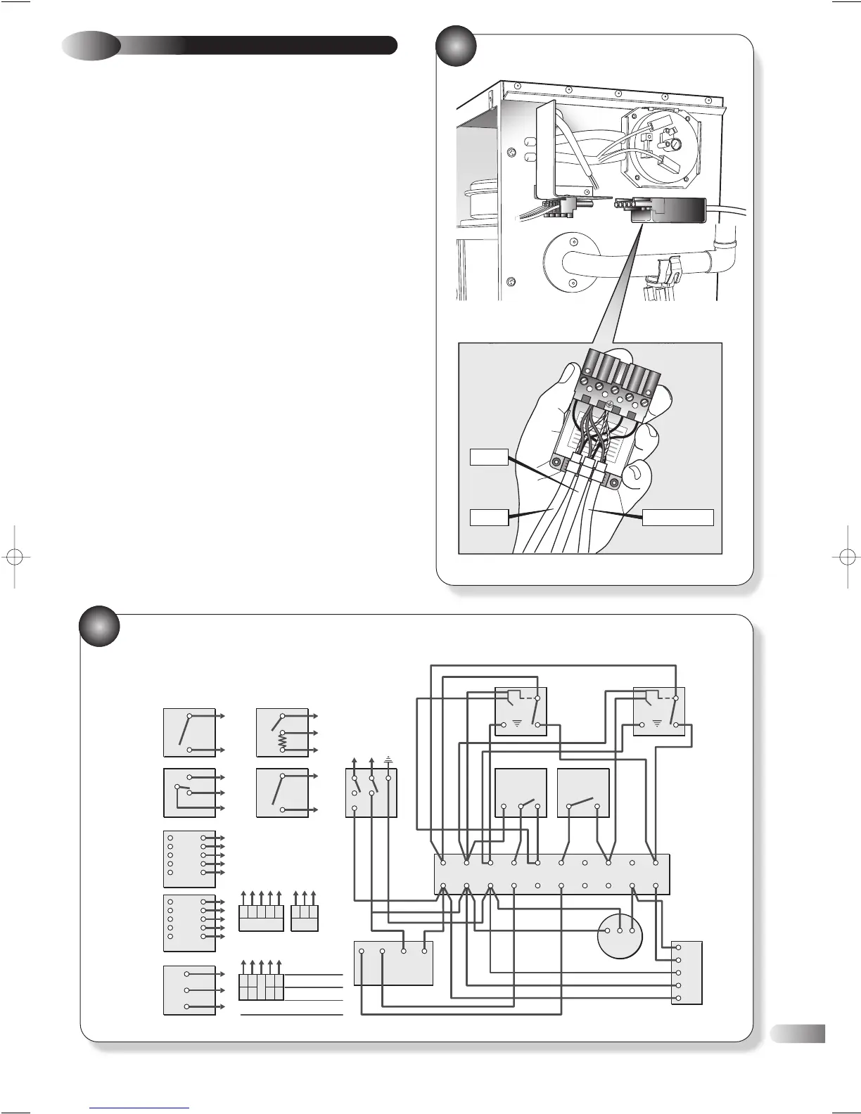
a) Remove the mains supply plug from the appliance and connect
the electricity supply, the pump supply and appropriate
external controls (using suitable cable) as described below
and with reference to Fig 22.
b) Connect the mains supply Live to terminal L1.
c) Connect the pump Live to terminal L2.
d) Connect the external control (timer / programmer) Live to
terminal L3.
e) If not connecting an external control, it is necessary to link a
switched live between terminals L1 and L3.
f) Ensure all wires are clamped within the plug and that outer
insulation is not cut back beyond the clamp.
g) Ensure all Earth wires are longer than the Live and Neutral to
ensure it will be last to be disconnected should excessive strain
be put on cables.
WIRING INSTRUCTIONS
If using 6-wire 28mm or 1” BSPV4043H on any circuit, white is not
needed and must be made electrically safe. The wiring shown is based
on the use of 10-way junction box (Honeywell Part No. 42002116-001).
Junction Box terminal 10 is switched live and terminal 9 is pump live.
CT200
ROOM
THERMOSTAT
L641A
CYLINDER
THERMOSTAT
V4043H
HEATING
VALVE
V4043H
HOT WATER
VALVE
230V mains
input
23