18
BS
!
"
#
$
%
&
/
(
(
)
BL
BM
BN
BO
BP
BQ
BR
BT
BU
CL
CL
CM
CN
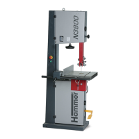
Bandsaw
N2-35
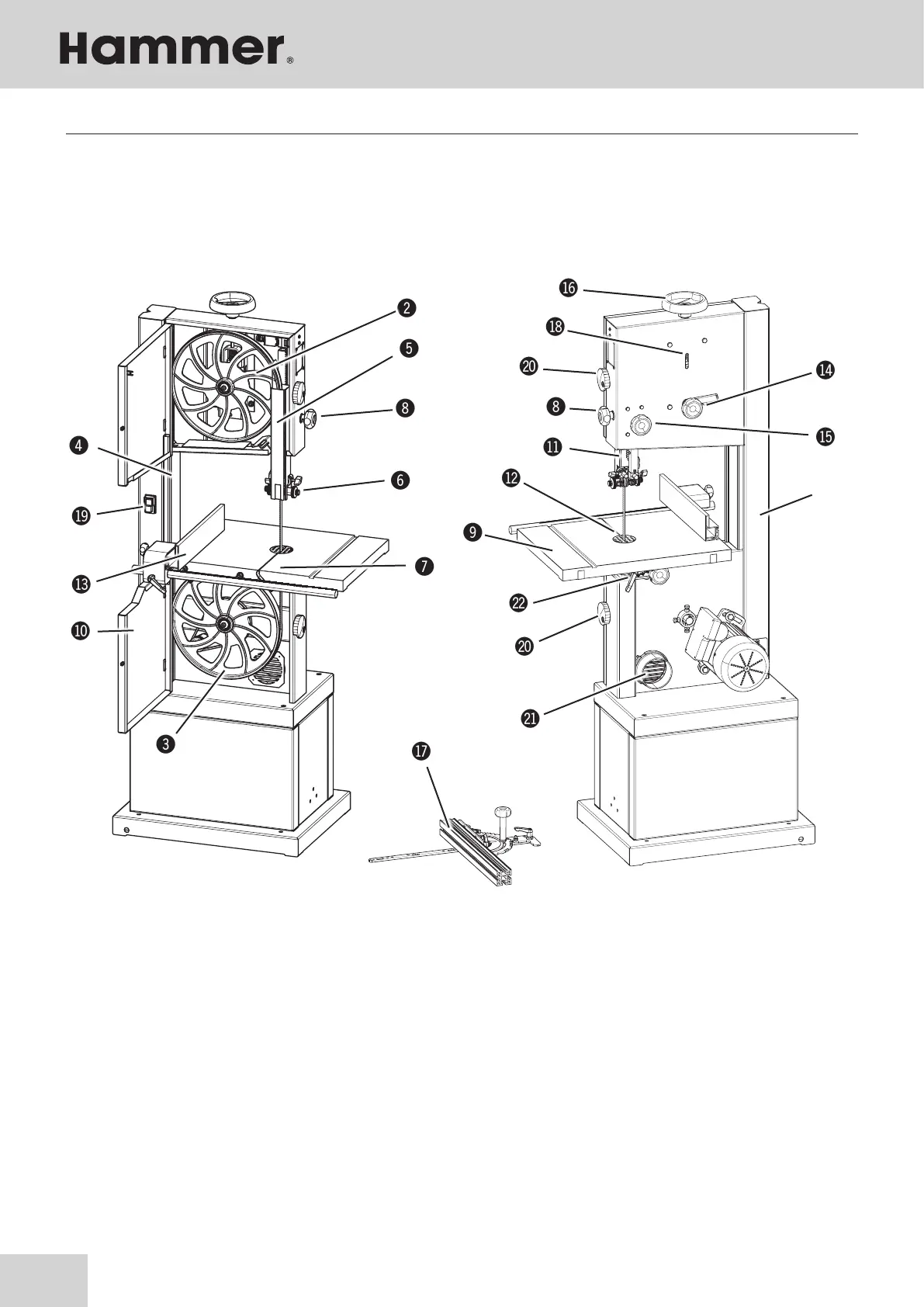
5 Setting up the machine
5.1 Overview
Fig. 5-1: Overview
BO Guide fence
BP
Saw blade track - Adjuster hand wheel and clam-
ping leverl
BQ Lock wheel - Blade guide height adjustment
BR Blade tension hand wheel
BS mitre fence (Accessories)
BT Saw blade tension indicator window
BU On/Off switch
CL Lock wheel - Wheel door
CM Vacuum connector
CN
Tiltable table (Adjuster hand wheel and clamping
lever)
! Machine base-frame
" Upper wheel
# Lower wheel
$ Rising part of saw blade
% Falling part of saw blade
& Upper blade guide
/ Lower blade guide (Optional)
* Blade guide height adjustment
) Work bench
BL Wheel door
BM Height adjustable protection device
BN Table insert
Setting up the machine