8
E
N
G
L
I
S
H
3.2 Operating Sequence
1. With master switch OFF (pushed in), turn disconnect
switch "DISC" to on. Control transformer "IT", and
crankcase heater "HTR", are energized. Power on light
(white) illuminates. "DRYER ENERGIZED" is indicated on
display. Disconnect switch "DISC" must be left on
except for maintenance reasons. Crankcase heater
"HTR" must be energized twenty-four (24) hours prior
to start up.
2. Pull master switch on. Display indicates STANDBY or
SYSTEM ENABLED.
3. To "START" turn momentary Stand-by/Auto selector
switch to AUTO and release.
a. If STANDBY is displayed and no fault condition
exists, motor starter "M" coil, liquid valve solenoid
"1SOL", and hot gas by-pass valve solenoid "2SOL",
are energized. Display indicates "PREPARING TO
RUN" followed by "DRYER RUNNING" or "COMP
LOADING". If "SYSTEM ENABLED" is displayed dryer
will pumpdown prior to valves energizing.
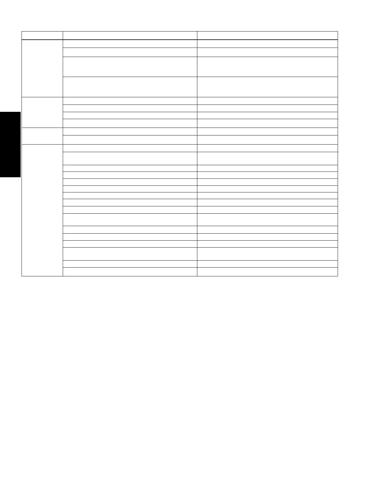
Condition Display Message
Dryer energized; Master Switch Off DRYER ENERGIZED
Dryer energized; Master Switch On STANDBY or SYSTEM ENABLED
Status Stand-by Selected Dryer will pump down if suction pressure is high
(indicated by "DRYER PUMPING DOWN") followed by
"STAND-BY"
Auto Selected PREPARING TO RUN followed by
COMPRESSOR LOADING and 33%, 50%, 66%, 75%
83%, or 100%
Refrigerant (low-side) Suction SUCTION PRESSURE
Pressures Refrigerant (high-side) Head HEAD PRESSURE
Compressed air at inlet to dryer INLET AIR PRESSURE
Optional - Differential pressure across dryer AIR PRESSURE DROP
Temperatures Optional - Compressed air at inlet to dryer INLET AIR TEMP
Optional - Lowest air temperature LOWEST AIR TEMP
Compressor Solid State Motor Protector Open SSMP-1MTR
Compressor Solid State Motor SSMP-2MTR
Protector Open (2nd Compressor)*
Motor Starter Protector Open MTR STARTER - 1MTR
Motor Starter Protector Open (2nd Compressor)* MTR STARTER - 2MTR
Low oil pressure OIL PRESSURE -1 MTR
Low oil pressure (2nd Compressor)* OIL PRESSURE - 2MTR
Low (low or suction) side refrigerant pressure LOW REFRIG PRESS
Faults High (high or head) side refrigerant pressure HIGH REFRIG PRESS
High evaporator air temperature HI EVAP AIR TEMP
Optional - Low water pressure LOW WATER PRESS
(water-cooled models)
Optional - High differential pressure CHECK SEPARATOR
Optional - Low evaporator air temperature LOW EVAP AIR TEMP
Optional - High condensate level (air-to-air drain) DRAIN 1 HIGH LEVEL
Optional - High condensate level (air-to- DRAIN 2 HIGH LEVEL
refrigerant drain
Optional - High condensate level (separator drain) DRAIN 3 HIGH LEVEL
Optional - High inlet compressed air temperature INLET AIR TEMP
* 50 HP and larger
b. As low side system pressure drops to unloader set
point(s), PLC output(s) energize solenoids(s) 3SOL
and 4SOL (35 HP and larger) which unload com-
pressor cylinder(s). As pressure rises above the
unloader set point(s), compressor will load in
reverse sequence. Percentage following "Com-
pressor Loading" indicates percentage of cylinders
loaded.
c. Compressor runs automatically unless a SSMP,
motor starter, low oil pressure, high head pressure,
or low suction pressure fault occurs.
4. To put in STANDBY turn momentary Stand-by/Auto
selector switch to STANDBY and release.
a. Display indicates "DRYER PUMPING DOWN".
b. Compressor motor "MTR" continues the pump
down cycle until low side system pressure reaches
the low pressure cutout point. At cutout point,
the PLC de-energizes motor starter "M" coil.
Display indicates STANDBY.
c. If low side system pressure rises to low pressure
set point, compressor starts and pumpdown
repeats automatically.
Operator Interface Display
 Loading...