79
Installation
Before starting
Operation
Screen block
diagram
Function setting Program System setting Specifications
[ Communication setting parameter ]
▶Communication setting
▶Hardware address setting
Select a communication protocol.
Select a communication speed.
Select a data length.
Enter a unit No.
Select a parity bit.
Enter response time.
Select a stop bit.
Parameter Default Setting range
Communication protocol MODBUS RTU PCLINK, PCLINK+SUM, MODBUS ASC, MODBUS RTU
Communication speed 115200 9600, 19200, 38400, 57600, 115200
Stop bit 1 1, 2
Data length 8 7, 8
Parity bit NONE NONE, EVEN, ODD
Unit No. 1
1 - 99 (Up 32 units can be connected, including master).
Response time 0 ㎳ 0 ~ 100 ㎳
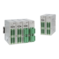
- Screen to set hardware state of control module.
- Normal operation is enabled by matching hardware settings of control and input/output modules.
If incorrect address is set for an output module, it may malfunction.
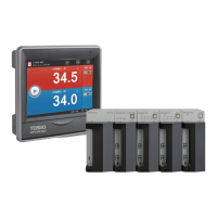
1. TD510 display and communication are normal.
2. TD510 display and communication are abnormal.
3. Input/output module and communication are normal.
4. Input/output module and communication are abnormal.
① ②③ ④
Fig. 134) Communication setting screen
Fig. 135) Hardware address 1
Fig. 136) Hardware address 2
 Loading...