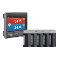
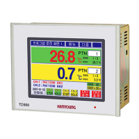
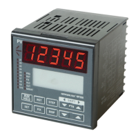
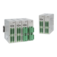
Programmable Temperature & Humidity Controller
82
Specifications
1. Input specifications
Input type Measuring range (℃) Level
Thermoresistor
(RTD)
Pt100 Ω Pt-1
-200.0 ~ 640.0
±0.1 % of FS
±1 Digit
KPt100 Ω
KPt-1
-200.0 ~ 500.0
Thermocouple
(TC)
K
K-0
-200 ~ 1370
±0.15 % of FS ±1 digit
K-1
-200.0 ~ 1370.0
±0.15 % of FS ±1 digit(*2)
J
-200.0 ~ 1200.0
±0.15 % of FS ±1 digit(*2)
E
-200.0 ~ 1000.0
±0.15 % of FS ±1 digit(*2)
T
-200.0 ~ 400.0
±0.15 % of FS ±1 digit(*3)
R
0.0 ~ 1700.0
±0.15 % of FS ±1 digit(*4)
B
0.0 ~ 1800.0
±0.15 % of FS ±1 digit(*1)
S
0.0 ~ 1700.0
±0.15 % of FS ±1 digit(*4)
L
-200.0 ~ 900.0
±0.15 % of FS ±1 digit(*2)
N
-200.0 ~ 1300.0
±0.15 % of FS ±1 digit(*3)
U
-200.0 ~ 400.0
±0.15 % of FS ±1 digit(*3)
Wre 5-26
0.0 ~ 2300.0
±0.15 % of FS ±1 digit(*4)
DC voltage
(VDC)
-10 - 20 mV
-10.00 ~ 20.00
±0.1 % of FS
±1 Digit
0 - 100 mV
0.00 ~ 100.00
1 - 5 V
1.00 ~ 5.00
0 - 30 V
0.00 ~ 30.00
[ Range configuration by input type ]
2. Hardware specifications
▶ Power input
Power voltage 100 – 240 V a.c. Voltage regulation ±10 %
Power frequency 50 – 60 ㎐
Power consumption 20 VA max
Max. rating of internal fuse
250 V a.c.
Dielectric strength
Between 1st and 2nd terminals : Min. 1500 V a.c for 1 min
Between 1st and FG terminals : Min. 1500 V a.c for 1 min
Between 2nd and FG terminals : Min. 1500 V a.c for 1 min
Insulation resistance 20 ㏁ or 500 V d.c. between power and FG terminals
(*1) 0 ~ 400 ℃ : ±5 % of FS ±1 digit
(*2) -200 ~ -150 ℃ : ±0.2 % of FS ±1 digit
(*3) -200 ~ -150 ℃ : ±0.4 % of FS ±1 digit, -150 ~ -100 ℃ : ±0.2 % of FS ±1 digit
(*4) 0 ~ 200 ℃ : ±0.2 % of FS ±1 digit
 Loading...