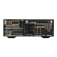
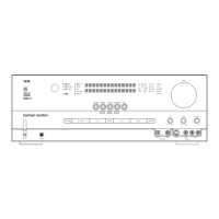
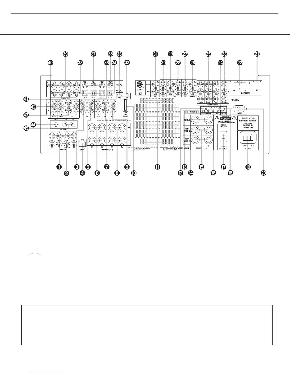
8 REAR-PANEL CONNECTIONS
REAR-PANEL CONNECTIONS
0 Preamp Outputs
1 Subwoofer Output
2 Tape Outputs
3 A-BUS Connector
4 Tape Inputs
5 Surround Speaker Outputs
6 CD Audio Input
7 Front Speaker Outputs
8 Multiroom Audio Outputs
9 Digital Media Player (DMP) Input
A Fan Vents
B Full Carrier IR Output
C IR Output
D Center Channel Speaker Outputs
E Surround Back/Multiroom Speaker Outputs
F IR Input
G Switched AC Accessory Outlet
H Trigger Output
I AC Power Cord Socket
J RS-232 Port
K HDMI Output
L HDMI Inputs
M Component Video Monitor Outputs
N Multiroom IR Input
O Component Video Inputs
P Video Monitor Outputs
Q DVD Video Inputs
R Video 1 Video Inputs
S Video 1 Video Outputs
T Video 2 Video Inputs
U Video 3 Video Inputs
V XM-Ready Module Input
W USB Connector
X Optical Digital Audio Output
Y Coaxial Digital Audio Output
Z DVD Audio Inputs
a Coaxial Digital Audio Inputs
b Optical Digital Audio Inputs
c 8-Channel Direct Inputs
d Video 1 Audio Inputs
e Video 2 Audio Inputs
f Video 3 Audio Inputs
g Video 1 Audio Outputs
h FM Antenna Jack
i AM Antenna Connections
NOTE: To assist in making the correct connections for
multichannel input, output and speaker connections,
all connection jacks and terminals are color-coded
as follows:
Front Left: White
Front Right: Red
Center: Green
Surround Left: Blue
Surround Right: Gray
Surround Back Left: Brown
Surround Back Right: Tan
Subwoofer: Purple
Coaxial Digital Audio: Orange
Composite Video: Yellow
Component Video “Y”: Green
Component Video “Pr”: Red
Component Video “Pb”: Blue
Optical Digital In: Black
Optical Digital Out: Gray
REAR-PANEL CONNECTIONS
8 REAR-PANEL CONNECTIONS
NOTE: To make it easier to follow the instructions that refer to this illustration, a larger copy may be downloaded from the Product Support section for this product at
www.harmankardon.com.
HKP1445AVR645om 6/7/06 6:33 PM Page 8
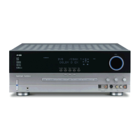
AVR645
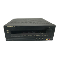
harman/kardon
 Loading...