Appendix C Encoder Back Panel Slot Specifications Additional Module Configurations for FLEX-based Encoders
© 2015 Harmonic Inc. All rights reserved. 84 Electra 9200, Rev O
Additional Module Configurations for FLEX-based Encoders
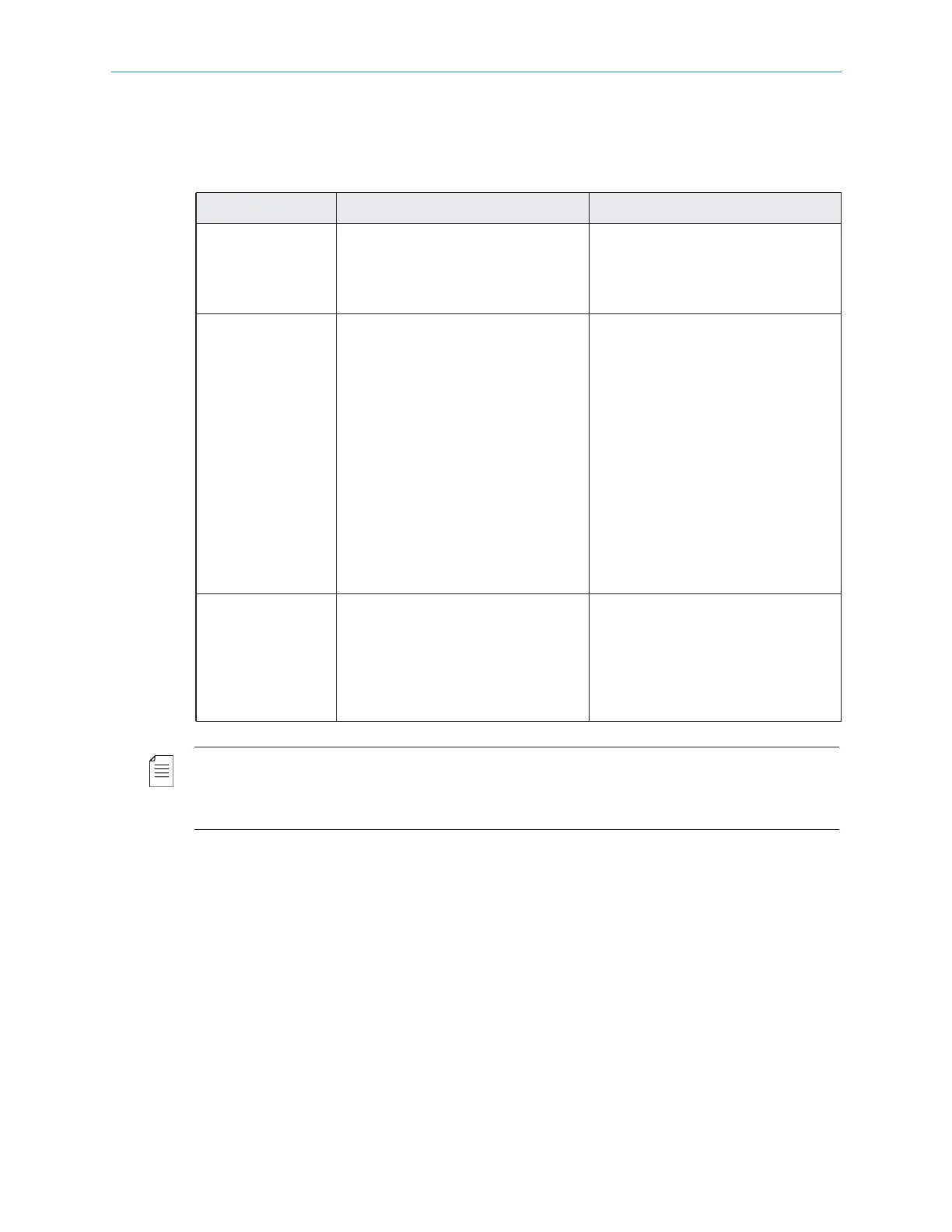
Table C–3 lists the module configurations available for FLEX-based encoders.
NOTE: ASI Input modules (used with the FLEX-1 Module) and ASI Output modules utilize the same
hardware, but perform different functions based on; 1) the slot number and 2) if a FLEX-1 Module is
installed. If installed in slots #2 or 5 the ASI module is always an output, If a FLEX-1 Module is
installed, an ASI module installed in slots #1 or 3 is an input.
Table C–3: FLEX-1 Module Options
Module Option Notes
FLEX
n Slot #4 must be populated
first.
n Slot #5 is populated second.
(1-2 modules per chassis)
ASI Input n Slot #1 (typical), slot #3 if slot
1 is already in use.
n ASI input modules cannot use
slot #4 as it is used for first
FLEX module.
(1 card per chassis)
n For FLEX only chassis, the
FLEX-1 Module goes into slot
#4 and #5. Slot #4 must be
populated first.
n For baseband and
compressed mixed input
encoders, the FLEX-1 Module
can be either slot #4 or #5.
ASI input is currently only for
FLEX module. ASI in slots 1, 3,
and 4 appears as an input card.
RF 8VSB n Slot #1 (typical).
n Slot #3 if slot 1 is already in
use.
n Slot#2ifslots 1 and 3 are
already in use.
(1 card per chassis)