Chapter 5 Maintenance and Troubleshooting Input/Output Modules
© 2015 Harmonic Inc. All rights reserved. 45 Electra 9200, Rev O
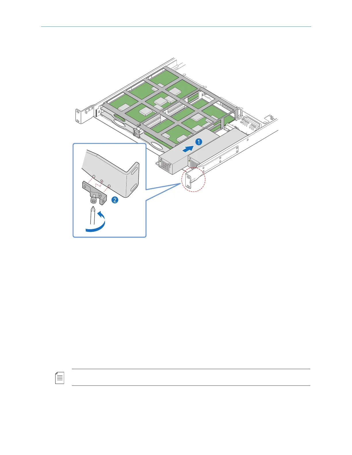
To replace a power supply:
1. With the bezel and fan tray assembly removed, insert the power supply into the chassis
until it engages with the connector, as shown in Figure 5–9.
Figure 5–9: Replacing a Power Supply
2. If necessary, use a Phillips-head screwdriver to attach the bracket to the right inside of the
chassis, as shown in Figure 5–9.
3. Reinst all the fan tray assembly, as described in Removing and Replacing the Fan Tray.
4. Reinst all the bezel, as described in Removing and Replacing the Bezel.
5. Connect power to the power supply.
Input/Output Modules
To extend the capability of the Electra 9200, there are 5 slots for optional input/output
modules in the rear of the chassis. These provide additional audio encoding capabilities,
audio & video decoding, or transport stream input/output options. Refer to Optional Features for
additional information on each of these modules.
NOTE: Before making changes to the FLEX-1 Module, make sure the service configuration is cleared
before powering down the system.
(RN-15)