Chapter 7 FLEX Decoding Module Cabling the FLEX-1 Module
© 2015 Harmonic Inc. All rights reserved. 63 Electra 9200, Rev O
Two Channel FLEX System
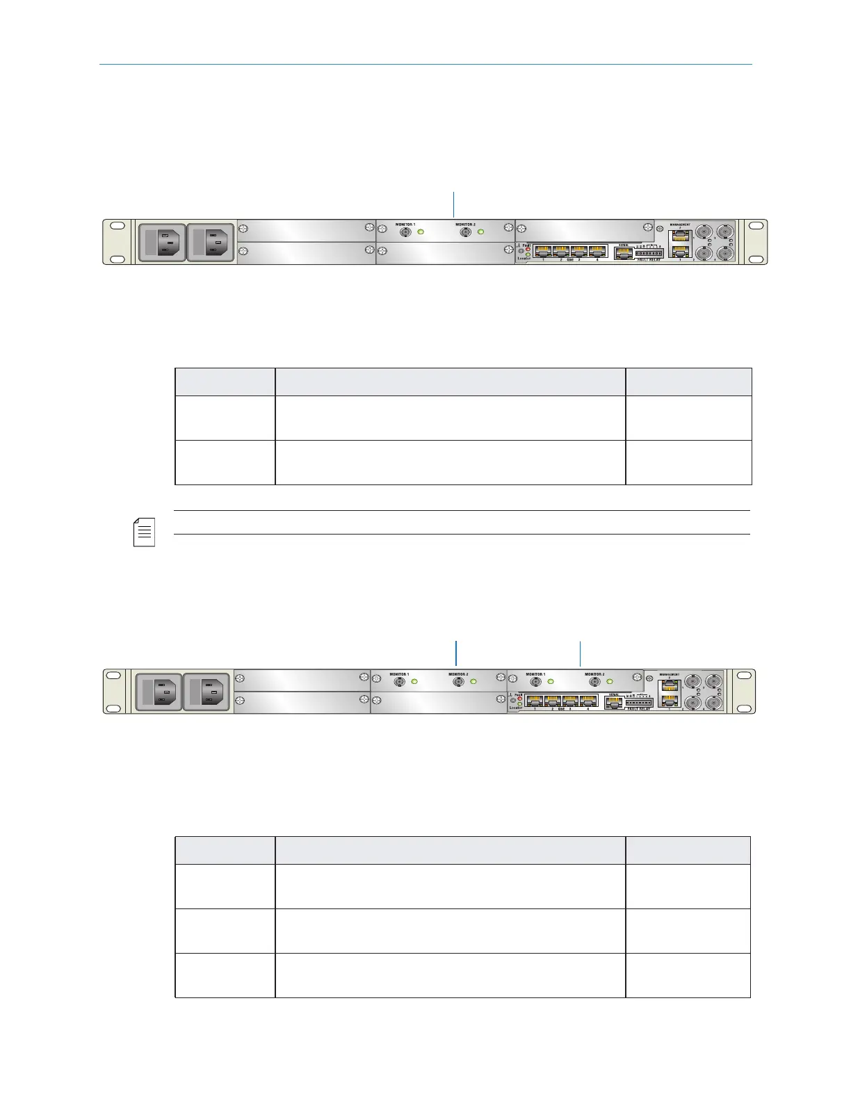
Figure 7–2 illustrates a typical 2-channel re-encode chassis cabling assignment. This setup
uses a one- or two-channel encoder chassis. Table 7–2 describes the port and cable
associations.
Figure 7–2: Two Channel Re-Encode Chassis (Cable) Setup
Table 7–2: Port and Cable Assignments (two-channel)
Port Description Connector
Monitor 1
Slot 4
75 cable. The Monitor 1 output port can be used
for monitoring and troubleshooting purposes.
DIN 1.0/2.3
Monitor 2
Slot 4
75 cable. The Monitor 2 output port can be used
for monitoring and troubleshooting purposes.
DIN 1.0/2.3
NOTE: The FLEX-1 Module in this configuration must use slot 4.
Four Channel FLEX System
Figure 7–3 illustrates a typical four channel re-encode chassis cabling assignment. This setup
uses a base three or four channel encoder chassis.
Figure 7–3: Four-Channel Re-Encode Chassis (Cable) Setup
Table 7–3: Port and Cable Assignments (four-channel)
Port Description Connector
Monitor 1
Slot 4
75 cable. The slot 4 Monitor 1 output port can be
used for monitoring and troubleshooting purposes.
DIN 1.0/2.3
Monitor 2
Slot 4
75 cable. The slot 4 Monitor 2 output port can be
used for monitoring and troubleshooting purposes.
DIN 1.0/2.3
Monitor 1
Slot 5
75 cable. The slot 5 Monitor 1 output port can be
used for monitoring and troubleshooting purposes.
DIN 1.0/2.3
Slot 4
(RN-22)
Slot 4
Slot 5
(RN-23)