HFS6801+ Installation and Operation Manual31
Chapter 3: Operation
1, 1 Y Gain Adjusts gain to the luminance channel -3.0 to 3.0 dB
(0.0)
1, 2 Cb Gain Adjusts gain to the Cb color difference
component
-3.0 to 3.0 dB
(0.0)
1, 3 Cr Gain Adjusts gain to the Cr color difference
component
-3.0 to 3.0 dB
(0.0)
1, 4 Black Clip Level Sets the black clip level -47.9 to 47.9 mV
(0.0)
1, 5 Black Clip Controls the activation of Black Clip
•Off
•On
1, 6 White Clip Level Sets the white clipping level 636.87 to 763.13 mV
(700.0)
1, 7 White Clip Controls the activation of White Clip
• Off
•On
1, 8 Hue Adjusts the hue of the incoming digital
video signal
-180 to 180 °
(0)
1, 9 Test Signal Enable Controls the activation of the internal test
signal generator
•Off
•On
1, A GL Lock Source Selects the reference source for the on-board
genlock circuit
• Card Ref
•Frame Ref
1, B In Field Detection Selects the input field detection by either
V-bit or F-bit
•V-bit
•F-bit
Remote Control Only
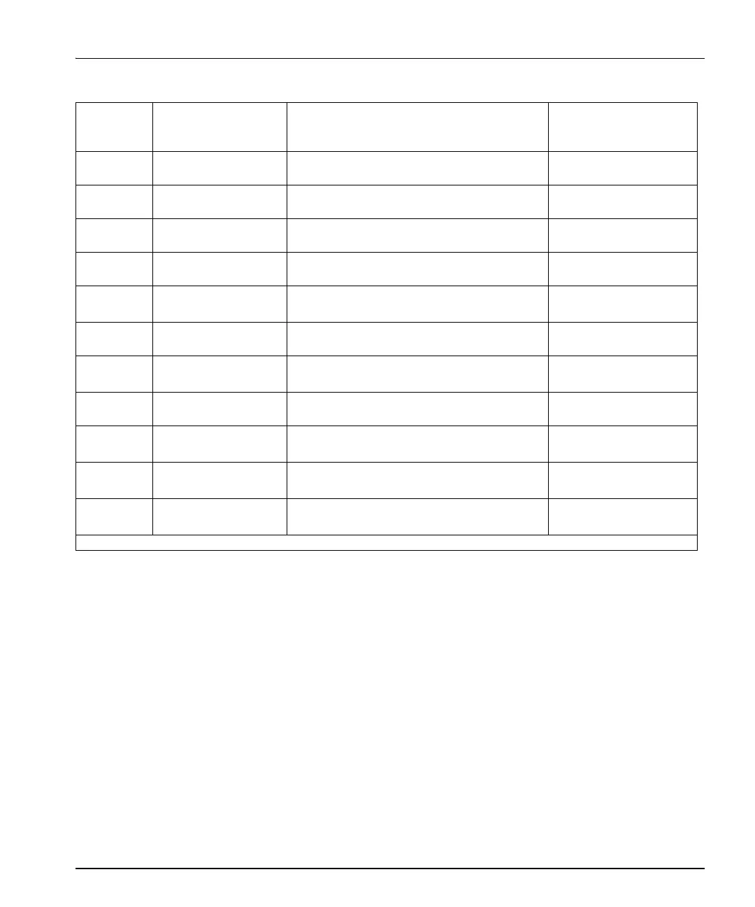
Table 3-3. Parameter Options (Continued)
Bank,
Rotary
Switch
Parameter Name Function Options