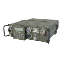
RF-5800H 125-WATT COMMUNICATION SYSTEM
INSTALLATION
2-5
Add a ground strap at one of the four locations between the lockwasher and the shock mount bottom plate.
For the four hole locations on the RF-5211VSM, attach to the vehicle in the following arrangement:
• Hex Bolt
• Shock mount bottom plate
• Vehicle body
• Flatwasher
• Lockwasher
• Hex Nut
Add a ground strap at one of the four locations between the flatwasher and the shock mount bottom plate or at the
ground stud located near the rear of the shock mount bottom plate. Refer to the RF-5211VSM outline and
installation drawing, Part Number (10372-0876) included with the shock mount for additional information.
2.5.4 Jumper/DIP Switch Settings
There are no jumper/DIP switch settings required when installing the RF-5800H 125-Watt Communication
System.
2.5.5 Unit Removal and Installation Procedures
See Figures 2-7, 2-8, and 2-9 for RF-5800H 125-Watt Communication System installation diagram.
2.5.6 System Cabling Interconnect Information
See Figures 2-10 and 2-11 for RF-5800H 125-Watt Communication System cabling interconnect diagrams.

 Loading...