RF-5800H 125-WATT COMMUNICATION SYSTEM
FUNCTIONAL DESCRIPTION
4-1
CHAPTER 4
FUNCTIONAL DESCRIPTION
4.1 INTRODUCTION
This chapter covers the functional description of the RF-5800H 125-Watt Communication System. Refer to
Chapter 6 for BIT and system troubleshooting information. The major function level description is divided into
the following three signal paths:
• RF/Audio Signal Path
• Control Path
• Power Distribution
The description of each signal type is further divided as each LRU relates to the signal path. Each signal type is
not present on every LRU, which will be apparent in the following paragraphs.
NOTE
For more detailed information, refer to the Level III
RF-5800H-MP and RF-5832H-PA Intermediate Maintenance
Manuals.
4.2 SIGNAL PATHS
4.2.1 RF/Audio Signal Path
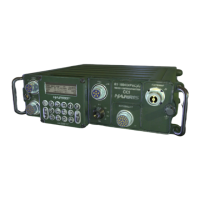
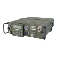
See Figure 4-1. The RF/Audio signal path begins at the handset connected to J1 on the RF-5800H-MP. The
RF-5800H-MP converts the analog audio appearing at J1 into RF. The RF output from the RF-5800H-MP at J7 is
routed via the R/T-PA Coaxial Cable Assembly to J12 of the RF-5832H-PA. The RF signal is amplified to 125
Watts by the RF-5832H-PA. The signal is then output at connector J11. If the optional RF-382A is used, the RF
signal is routed from J11 on the RF-5832H-PA to J1 of the RF-382A. The receive path is identical, except in the
reverse direction.
When an external speaker is used, audio is also routed via the data connector on the RF-5800H-MP to an external
loudspeaker or VIC-1 or VIC-3 VIS.
The external loudspeaker (optional for the vehicular system) contains an integrated audio amplifier and volume
control. The amplifier and speaker are capable of .5 watts minimum.
4.2.2 Control Path
See Figure 4-1. Control signals from the RF-5800H-MP are routed from J6 via the R/T-PA Control Cable
Assembly to J8 on the RF-5832H-PA. Coupler control signals are sent from J9 on the RF-5832H-PA to J2 on the
RF-382A (if used) via the PA-Coupler Control Cable Assembly.
4.2.3 Power Distribution Path
The following paragraphs describe the power distribution of the RF-5800H 125-Watt Communication System.
 Loading...