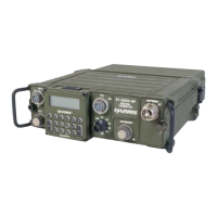
RF-5800H 125-WATT COMMUNICATION SYSTEM
TROUBLESHOOTING
6-11
6.4 TROUBLESHOOTING DIAGRAMS
6.4.1 General
Troubleshooting diagrams include the following:
• RF Signal Path Diagram – See Figure 4-1 for RF signals diagram.
• Control Path Diagram – See Figure 4-1 for control and data signals diagram.
• Power Distribution Diagram – See Figures 4-2 and 4-3 for power distribution diagram.
6.5 INTERCONNECT INFORMATION
6.5.1 General
For RF-5800H 125-Watt Communication System interconnect information, refer to Paragraph 2.5.6. For
connector pinouts, refer to the Level III maintenance manual.

 Loading...