RF-5800H 125-WATT COMMUNICATION SYSTEM
TABLE OF CONTENTS
v
LIST OF FIGURES
Figure Page
1-1 Typical RF-5800H 125-Watt Communication System
1-2 Maintenance Flow Chart 1-3. . . . . . . . . . . . . . . . . . . . . . . . . . . . . . . . . . . . . . . . . . . . .
1-3 Relationship of Units in RF-5800H 125-Watt Vehicular System
Typical Configuration 1-6. . . . . . . . . . . . . . . . . . . . . . . . . . . . . . . . . . . . . . . . . . . . .
1-4 RF-5800H 125-Watt Vehicular System Family Tree
Typical Configuration 1-7. . . . . . . . . . . . . . . . . . . . . . . . . . . . . . . . . . . . . . . . . . . . .
1-5 Relationship of Units in RF-5800H 125-Watt Base Station System
Typical Configuration 1-8. . . . . . . . . . . . . . . . . . . . . . . . . . . . . . . . . . . . . . . . . . . . .
1-6 RF-5800H 125-Watt Base Station System Family Tree
Typical Configuration 1-9. . . . . . . . . . . . . . . . . . . . . . . . . . . . . . . . . . . . . . . . . . . . .
1-7 Relationship of Units in the RF-5800H 125-Watt Transit Case System
Typical Configuration 1-10. . . . . . . . . . . . . . . . . . . . . . . . . . . . . . . . . . . . . . . . . . . . .
1-8 RF-5800H 125-Watt Transit Case System Family Tree Typical
Configuration 1-11. . . . . . . . . . . . . . . . . . . . . . . . . . . . . . . . . . . . . . . . . . . . . . . . . . . .
2-1 RF-5800H 125-Watt Vehicular System Installation and
Maintenance Clearances 2-7. . . . . . . . . . . . . . . . . . . . . . . . . . . . . . . . . . . . . . . . . .
2-2 RF-5800H-125 Watt Base Station Installation and Maintenance
Clearances 2-9. . . . . . . . . . . . . . . . . . . . . . . . . . . . . . . . . . . . . . . . . . . . . . . . . . . . . .
2-3 RF-5800H-125 Watt Transit Case Installation and Maintenance
Clearances 2-10. . . . . . . . . . . . . . . . . . . . . . . . . . . . . . . . . . . . . . . . . . . . . . . . . . . . . .
2-4 RF-5071VSM Shock Mount Dimensions 2-11. . . . . . . . . . . . . . . . . . . . . . . . . . . . . . . .
2-5 RF-5211VSM Shock Mount Dimensions 2-12. . . . . . . . . . . . . . . . . . . . . . . . . . . . . . . .
2-6 RF-5211-01VSM Shock Mount Dimensions 2-13. . . . . . . . . . . . . . . . . . . . . . . . . . . . .
2-7 RF-5800H 125-Watt Vehicular System Installation Typical
Configuration 2-15. . . . . . . . . . . . . . . . . . . . . . . . . . . . . . . . . . . . . . . . . . . . . . . . . . . .
2-8 RF-5800H 125-Watt Base Station System Installation
Typical Configuration 2-17. . . . . . . . . . . . . . . . . . . . . . . . . . . . . . . . . . . . . . . . . . . . .
2-9 RF-5800H 125-Watt Transit Case System Installation
Typical Configuration 2-19. . . . . . . . . . . . . . . . . . . . . . . . . . . . . . . . . . . . . . . . . . . . .
2-10 RF-5800H 125-Watt Vehicular System Cable Interconnects 2-21. . . . . . . . . . . . . . .
2-11 RF-5800H 125-Watt Base Station or Transit Case System Cable
Interconnects 2-22. . . . . . . . . . . . . . . . . . . . . . . . . . . . . . . . . . . . . . . . . . . . . . . . . . . .
4-1 RF-5800H 125-Watt Communication System RF/Audio and
Control Paths 4-3. . . . . . . . . . . . . . . . . . . . . . . . . . . . . . . . . . . . . . . . . . . . . . . . . . . .
4-2 Vehicular Power Distribution Diagram 4-4. . . . . . . . . . . . . . . . . . . . . . . . . . . . . . . . . .
4-3 Base Station or Transmit Case System Power Distribution Diagram 4-5. . . . . . . .
6-1 Troubleshooting Process Used in this Chapter 6-1. . . . . . . . . . . . . . . . . . . . . . . . . .
6-2 Sample Fault Code Display 6-6. . . . . . . . . . . . . . . . . . . . . . . . . . . . . . . . . . . . . . . . . . .
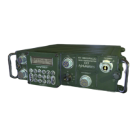
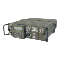
7-1 RF-5832H-PA 125-Watt Power Amplifier 7-5. . . . . . . . . . . . . . . . . . . . . . . . . . . . . . .
7-2 RF-5051PS Power Supply 7-6. . . . . . . . . . . . . . . . . . . . . . . . . . . . . . . . . . . . . . . . . . . .
7-3 RF-5071VSM Shock Mount Assembly 7-7. . . . . . . . . . . . . . . . . . . . . . . . . . . . . . . . .
7-4 RF-5211VSM Shock Mount Assembly 7-8. . . . . . . . . . . . . . . . . . . . . . . . . . . . . . . . . .
7-5 RF-5211-01VSM Shock Mount Assembly 7-9. . . . . . . . . . . . . . . . . . . . . . . . . . . . . . .
7-6 RF-5800H-125 Watt Base Station Mount Assembly
Typical Configuration 7-10. . . . . . . . . . . . . . . . . . . . . . . . . . . . . . . . . . . . . . . . . . . . .
7-7 RF-5800H-125 Watt Transit Case Mount Assembly
Typical Configuration 7-11. . . . . . . . . . . . . . . . . . . . . . . . . . . . . . . . . . . . . . . . . . . . .
7-8 R/T-PA Coaxial Cable Assembly (10181-9821) 7-12. . . . . . . . . . . . . . . . . . . . . . . . . .
 Loading...