12
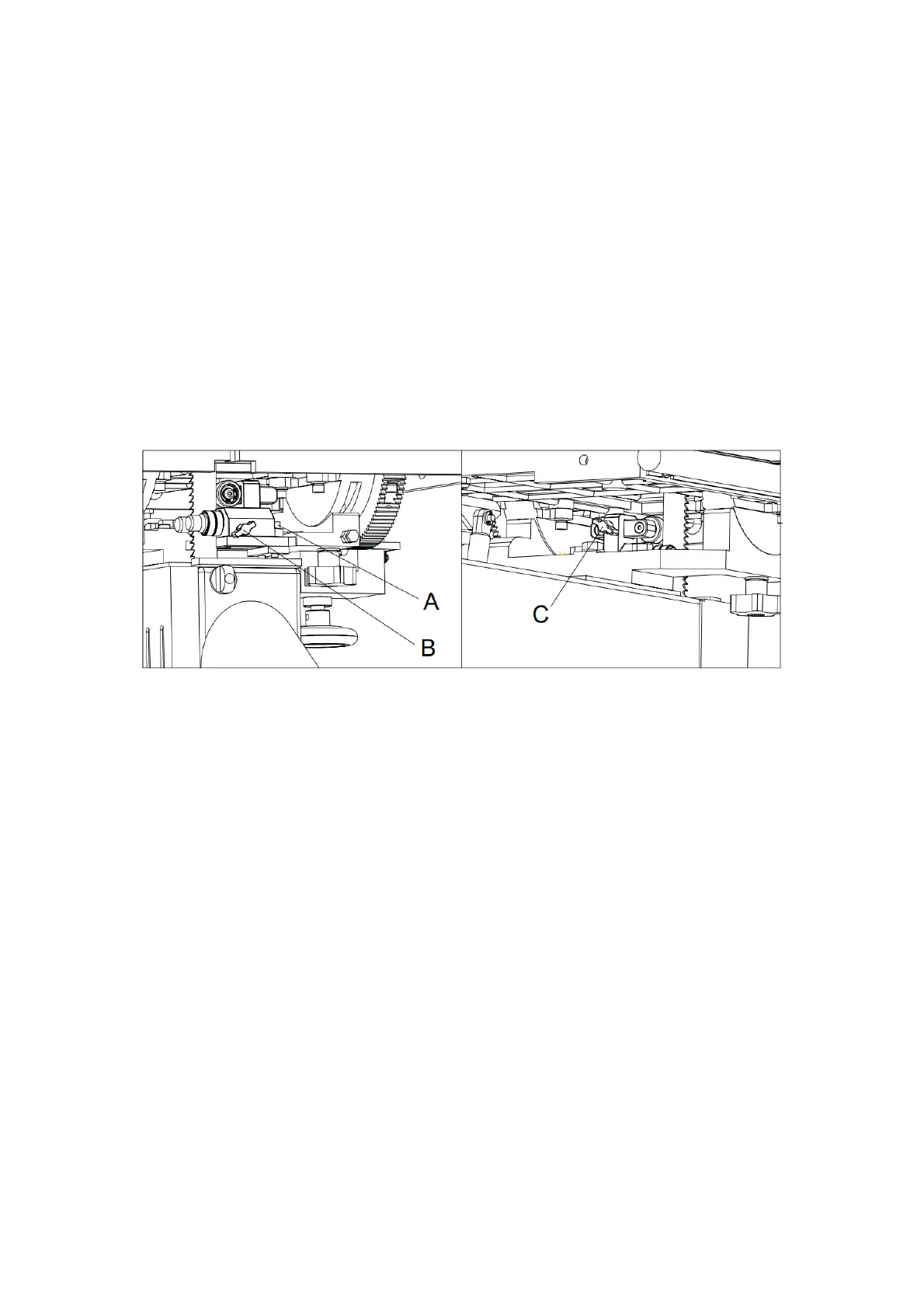
6.2.2 Lower Blade Guide
Refer to Figure 11.
1. Disconnect the machine from the power source.
2. Open the lower door and uninstall the lower blade guard by loosening the guard locking
knob.
3. Adjust the lower guide and thrust bearings below the table, using the similar procedure
as for the upper guides.
Loosen the locking screws (A) using a hex wrench to move the guide bearing bracket.
Loosen the locking knob (B) to adjust the guide bearings.
Loosen the locking knob (C) to adjust the thrust bearings.
4. Make sure all screws, knobs and levers are tightened when the adjustments are
complete.
Fig. 11
6.2.3 Guide Post
Refer to Figure 12.
1. Disconnect the machine from the power source.
2. Loosen the locking handle (A) and raise or lower the guide post by rotating the hand
wheel (B).
3. Position the blade guide assembly until the bottom of the guide bearings are about 3/16”
above the material to be cut. Or, lower the guide post until the scale pointer indicates the
height of your workpiece. This provides minimal clearance between the workpiece and
the bottom of the guide bearings, which will minimize blade deflection as well as
enhance operator safety.
4. Tighten the locking handle (A).
6.2.4 Guide Post Parallelism
The guide post should be parallel to the blade throughout the travel of the guide post. The
guide bearings will maintain the gap to the blade at any height and won’t have to be re-set
each time the guide post is moved. This setting has been accurately made by the
manufacturer and should not require immediate attention, but it may be checked in the future
as follows: